


Quick Research
Generate reliable direction feasibility study reports for your R&D in just a few steps.

Technical Q&A
Discover and master advanced knowledge NOW. Basics, ideas, possibilities, all at once.

Find Solutions
As an expert in R&D theories, this can generate solutions to your technical problems instantly.

Evaluate Feasibility
Analyze your overall solution with one click, know your potential R&D risks in advance.

Monitor Landscape
Get weekly tech updates, stay abreast of the latest tech innovations and key insights.
Lighting apparatus, display apparatus, projection display apparatus, lighting method, image display method and image projection method
A technology for lighting devices and display devices, which is applied in the field of image projection and can solve problems such as low light utilization efficiency
- Summary
- Abstract
- Description
- Claims
- Application Information
AI Technical Summary
Problems solved by technology
Method used
Image


Examples
no. 1 example
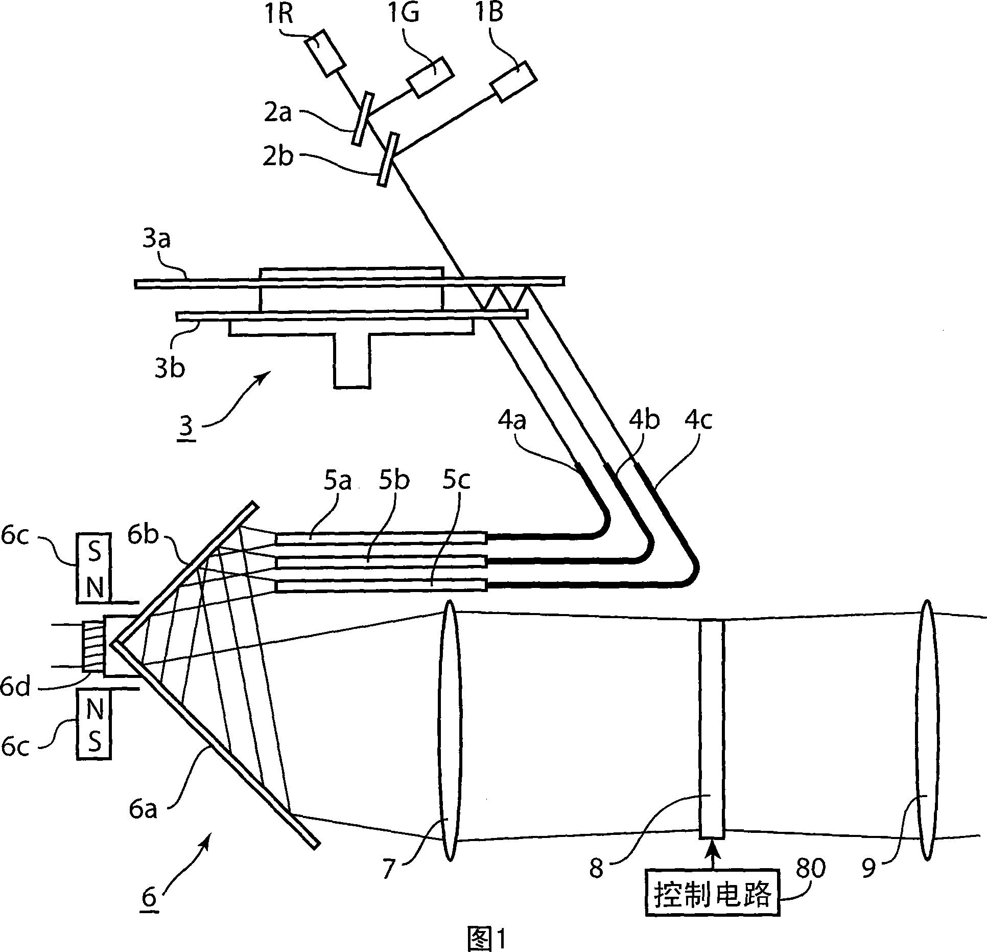
[0030] 1 is a cross-sectional view showing a schematic configuration of a projection display device according to a first embodiment of the present invention. In FIG. 1 , 1R represents a red laser light source emitting red laser light, 1G represents a green laser light source emitting green laser light, and 1B represents a blue laser light source emitting blue laser light.
[0031] 2a and 2b represent dichroic mirrors, and dichroic mirror 2a transmits red light and reflects green light. The dichroic mirror 2b reflects blue light and transmits red light and green light.
[0032] 3 denotes a color wheel, which is composed of a first disk body 3a and a second disk body 3b, and is arranged in the optical path of light emitted from the light sources 1R, 1G, and 1B.
[0033] 4a, 4b, and 4c represent light guides, which receive light of any color passing through the color wheel 3 at one end and emit it from the other end.
[0034] 5a, 5b, 5c denote rod integrators (rod integrators),...
no. 2 example
[0068] 8 is a cross-sectional view showing a schematic configuration of an optical path switching member in a projection display device according to a second embodiment of the present invention. In FIG. 8 , 17 a , 17 b , and 17 c denote red light, green light, and blue light emitted from three laser light sources not shown, respectively. 18a, 18b, and 18c represent optical deflectors, and acousto-optical elements or electro-optic elements, or galvano mirrors or micro mirror devices can be preferably used. The three light deflectors 18a to 18c change the advancing direction of the incident light according to the action of diffraction, refraction and reflection in response to external input. 19a and 19b represent dichroic mirrors, 20 represents lenses, 21a to 21f represent 6 light guides, 22a to 22f represent 6 rod integrators, 3 in the vertical direction and 3 in the left and right directions, a total of 6, Installed at specified intervals facing the sides in the longitudinal ...
no. 3 example
[0074] 9 is a cross-sectional view showing a schematic configuration of an optical path switching member in a projection display device according to a third embodiment of the present invention. In this third embodiment, the light is emitted from the transmission surface of the second disk body during the multiple reflections between the rotating first disk body and the second disk body, and by letting it enter Light guide for light path switching. In addition, in the third embodiment, by allowing the light emitted from the red, green and blue light sources to enter different positions on the first disc body, it is unnecessary to use the splitter used in the first embodiment of the present invention. color mirror.
[0075] In FIG. 9 , 24 denotes a color wheel, which is composed of a first disk body 24 a and a second disk body 24 b. The first disk body 24a and the second disk body 24b are fixed to the rotation shaft of the motor 24c while being aligned with their centers and m...
PUM
 Abstract
Description
Claims
Application Information
 - R&D Engineer
- R&D Manager
- IP Professional
- Industry Leading Data Capabilities
- Powerful AI technology
- Patent DNA Extraction
Browse by: Latest US Patents, China's latest patents, Technical Efficacy Thesaurus, Application Domain, Technology Topic, Popular Technical Reports.
© 2024 PatSnap. All rights reserved.Legal|Privacy policy|Modern Slavery Act Transparency Statement|Sitemap|About US| Contact US: help@patsnap.com