Precise magnetic flowage polishing system for optics parts and method thereof
A technology for precision polishing and optical parts, applied in the direction of optical surface grinders, grinding/polishing equipment, grinding machines, etc., can solve the problems of high manufacturing cost and low material removal efficiency, achieve convenient operation, high processing efficiency, and improve processing efficiency Effect
- Summary
- Abstract
- Description
- Claims
- Application Information
AI Technical Summary
Problems solved by technology
Method used
Image
Examples
Embodiment 1
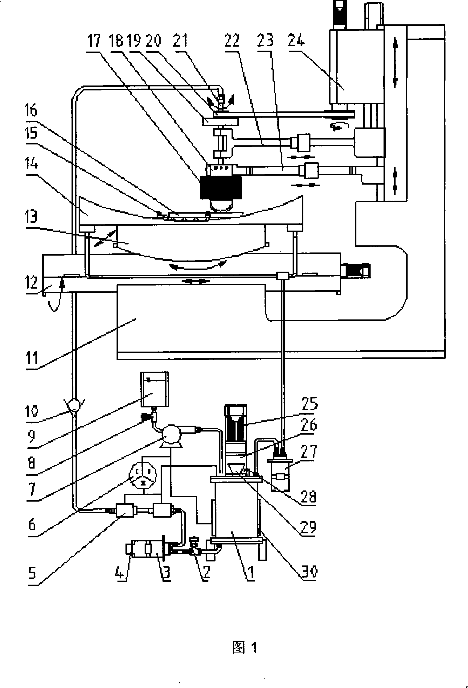
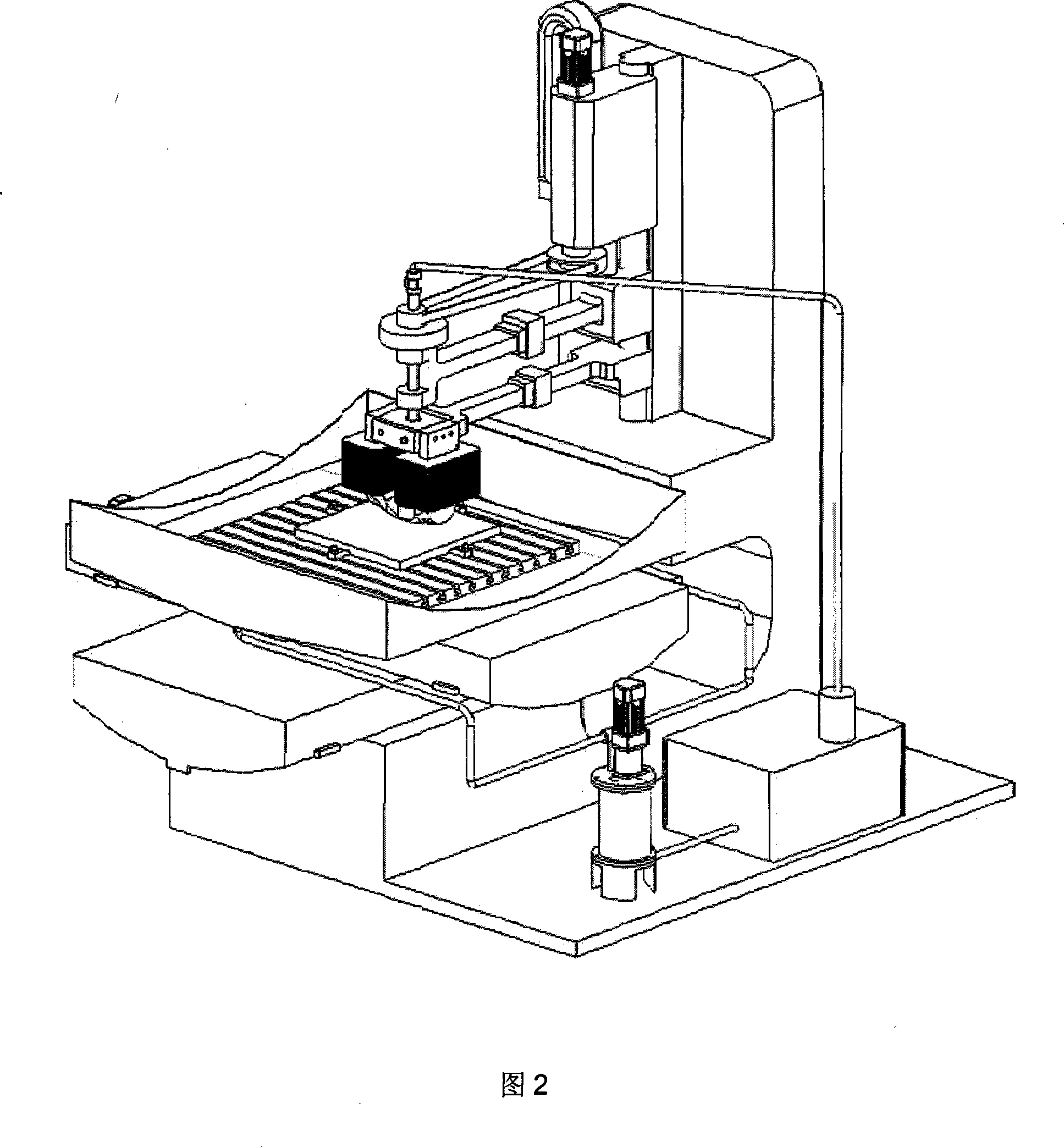
[0044] Embodiment 1, as shown in Figure 1, the device for magnetorheological precision polishing of optical parts is mainly composed of a spindle device, a numerical control platform device and a liquid circulation device. The main shaft and the two shafts are fixedly connected by the main shaft connecting device, and the polishing head is installed on the polishing main shaft. Speed, the spindle device moves along the Z-axis direction to adjust the relative distance between the polishing head and the workpiece, and the magnetic field generator around the polishing head is connected to the spindle device, and the electromagnetic coil is connected to a controllable DC power supply, which is generated in the processing area after power on. Gradient magnetic field, the magnetic field strength is controlled by adjusting the current strength, the rotational speed of the polishing spindle is ≥1000 rpm, and the magnetic field strength is ≥0.2 Tesla. The liquid circulation device is c...
Embodiment 2
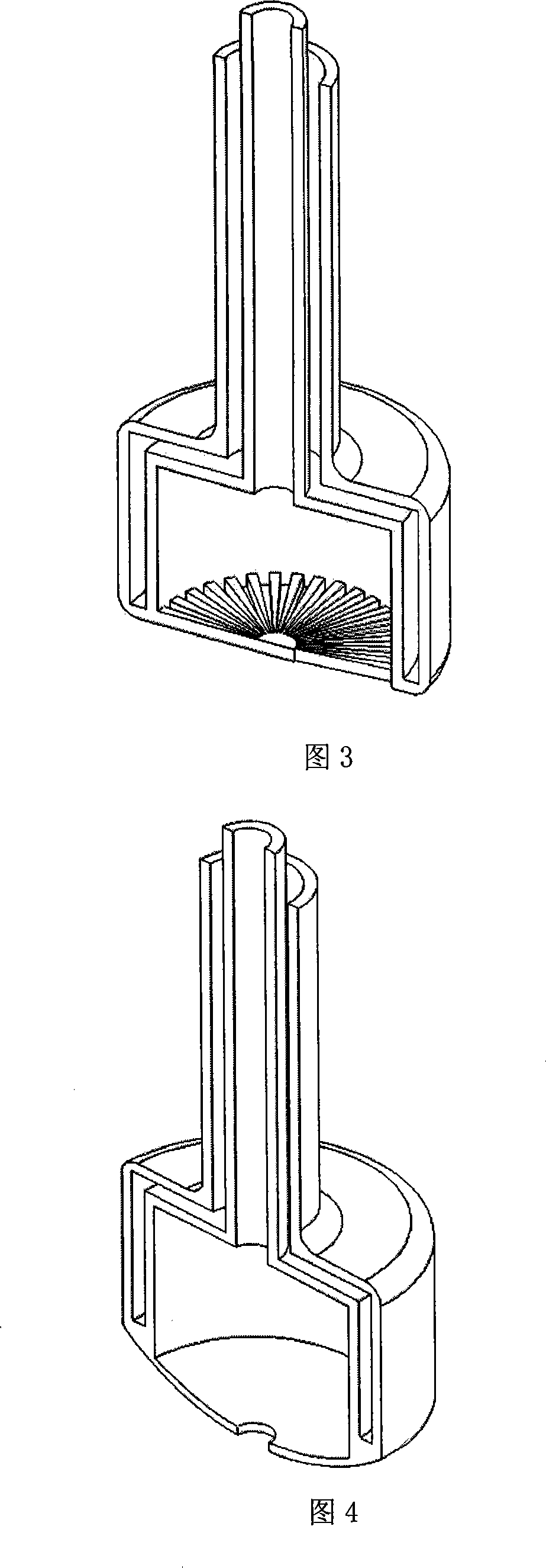
[0047] Embodiment 2: The overall device and composition of this embodiment are the same as that of specific embodiment 1, the difference is that a small-sized single-point polishing head with a convex curved surface is used to replace a large-sized multi-point polishing head on a plane for polishing. The polishing method and steps of this embodiment As follows: Install large-size flat optical parts on the workbench, position and clamp the optical parts; The head reaches the initial processing position, and adjust the distance between the polishing spindle and the workpiece; close the shut-off valve, add the magnetorheological liquid to the liquid storage tank, open the shut-off valve and start the delivery peristaltic pump, and the magnetorheological fluid passes through the silicone hose Then enter the polishing head with the rotary joint, then fill the gap between the polishing head and the workpiece, and finally enter the recovery device, start the recovery peristaltic pump ...
Embodiment 3
[0048] Embodiment 3: this embodiment is identical with specific embodiment 1 overall device and composition, as shown in Figure 14, and difference is to replace plane large-size optical part with curved surface large-size optical part, so described polishing head should be large Surface single-point polishing head and small-sized curved surface single-point polishing head, the body platform is mainly composed of frame, workbench, X-axis workbench, Y-axis workbench, Z-axis slide table and clamping components, and the workpiece is installed on the workbench In addition, the spindle device cooperates with the Z-axis slide table. In addition to moving, the X table and Y table can also realize the swing around the axis. Through the linkage of multiple degrees of freedom, the polishing process at any position in the workpiece space can be realized.
[0049] The polishing method and steps of this embodiment are as follows: install the large-size curved surface optical parts on the wor...
PUM
 Abstract
Description
Claims
Application Information
 - R&D
- Intellectual Property
- Life Sciences
- Materials
- Tech Scout
- Unparalleled Data Quality
- Higher Quality Content
- 60% Fewer Hallucinations
Browse by: Latest US Patents, China's latest patents, Technical Efficacy Thesaurus, Application Domain, Technology Topic, Popular Technical Reports.
© 2025 PatSnap. All rights reserved.Legal|Privacy policy|Modern Slavery Act Transparency Statement|Sitemap|About US| Contact US: help@patsnap.com


