Gas discharge lamp ignition

A technology of gas discharge lamps and gas discharge, which is applied in the use of gas discharge lamps, electric light sources, electrical components, etc., and can solve problems such as expensive power supply voltage

Inactive Publication Date: 2008-07-02
KONINKLIJKE PHILIPS NV
View PDF2 Cites 0 Cited by
  • Summary
  • Abstract
  • Description
  • Claims
  • Application Information

AI Technical Summary

Problems solved by technology

As a result a dedicated expensive cable is required to connect the feed circuit part to the lamp unit
A further disadvantage of the prior art is that in many cases, supply voltages with high frequencies, e.g. above 2 MHz, are expensive

Method used


Image

  • Gas discharge lamp ignition

Examples


Embodiment Construction

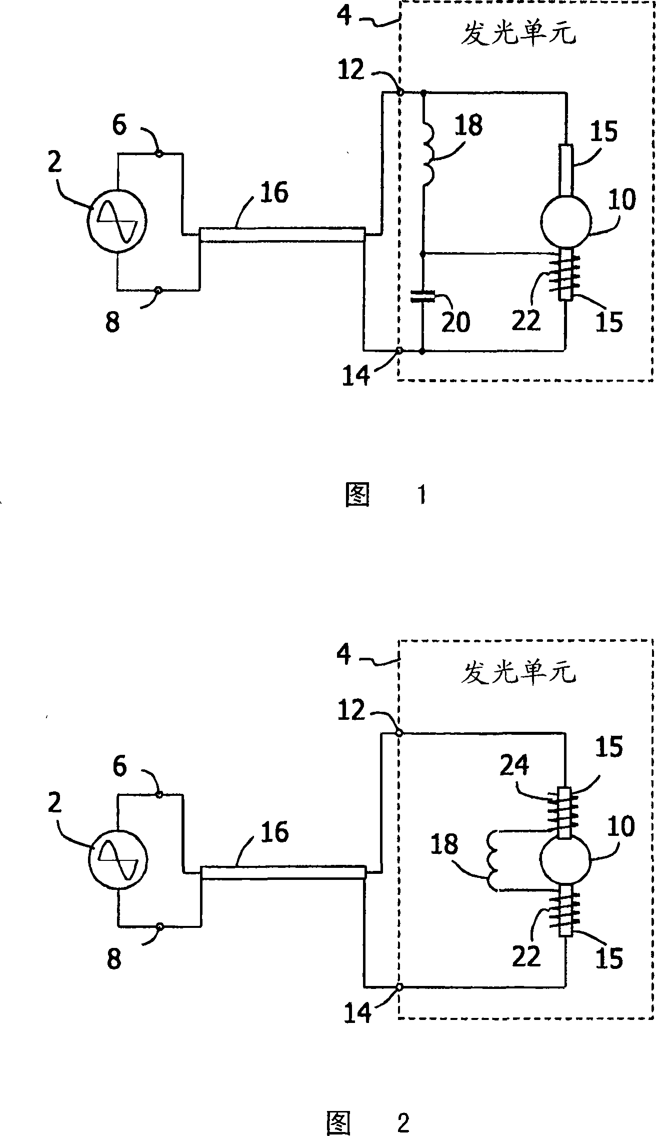
[0013] Fig. 1 shows a first embodiment of a lighting system to which the present invention is applied. The system includes a power supply device 2 and a light emitting unit 4 as main parts. The power supply unit 2 supplies its terminals 6 , 8 with an alternating voltage. The lighting unit 4 comprises a gas discharge lamp 10 having a space or container containing a gas and two internal electrodes connected to terminals 12 and 14 of the lighting unit 4 .

[0014] On opposite sides of the lamp 10 there may be an elongated sealing member 15 having a cavity containing a gaseous component such as mercury vapor. A foil such as molybdenum extends along the length of the cavity. An arrangement comprising such a sealing member 15 is called a UV enhancer. US 6,563,267 discloses the use of UV enhancers. Such UV-enhancers contain means for facilitating activation as a source of UV radiation when a voltage is applied across the cavity.

[0015] It should be noted that the invention sho...


PUM


Abstract

Ignition of a gas discharge lamp 10, which has a gas containing main space and two inner electrodes, of a lighting unit 4 of a lighting system is achieved by the use of a high frequency resonance circuit. The resonance circuit is connected to the inner electrodes and to a supply device 2, which supplies an alternating supply voltage. An outer electrode 22 is arranged near one the inner electrodes and to a node of the resonance circuit. Upon supplying the supply voltage a high voltage alternating burst will be generated at the outer electrode. This will result into a discharge of the gas in the main space. In turn, this will induce a discharge of the remaining gas. Then the frequency of the supply voltage will increase and a small reactive current only will remain to flow through the resonance circuit.

Description

technical field [0001] The present invention relates to the ignition method of the gas discharge lamp as described in the preamble of claim 1 and claim 6 respectively, and to the light source unit and the lighting system as described in the preamble of claim 12 and claim 16 respectively. Background technique [0002] US 6,734,643 discloses a lighting system comprising a feed circuit part, a lamp unit comprising a gas discharge lamp and a starting circuit. The starting circuit is divided into a starting driving part, which is included in the feeding circuit part, and a high voltage generating part, which is included in the lamp unit. The feeding circuit part further includes a feeding circuit for applying an alternating power supply voltage to the lamp unit, and a starting drive part. The lamp unit includes a lamp and a high voltage generating section. The internal electrodes of the lamp are connected to the power supply through the two terminals of the lamp unit and the tw...

Claims


Application Information

Patent Timeline
Patent Type & Authority Applications(China)
IPC IPC(8): H05B41/288H05B41/04
CPCH05B41/042Y02B20/204H05B41/2881Y02B20/00
Inventor C·德佩P·卢尔肯斯R·杜兰
Owner KONINKLIJKE PHILIPS NV
Why Eureka
Try Eureka