Signal processing circuit

A signal processing circuit, input signal technology, applied in the direction of TV, color TV, electrical components, etc., can solve problems such as the inability to correctly express the amplitude of pulse-shaped signals, and achieve the effect of suppressing deviation

Inactive Publication Date: 2012-06-27
SANYO ELECTRIC CO LTD +1
View PDF6 Cites 0 Cited by
  • Summary
  • Abstract
  • Description
  • Claims
  • Application Information

AI Technical Summary

Problems solved by technology

[0005] However, since the overshoot occurs near the rising edge of the input signal SIG, and the undershoot occurs at the falling edge of the input signal SIG, if the phase of the input signal SIG and the reference clock CLK only slightly deviates, then as Figure 9 As shown, the sampling timing becomes the rising edge and falling edge of the input signal SIG, and the sampling value cannot accurately express the amplitude of the pulse signal.

Method used


Image

  • Signal processing circuit
  • Signal processing circuit
  • Signal processing circuit

Examples


Embodiment Construction

[0021] (device structure)

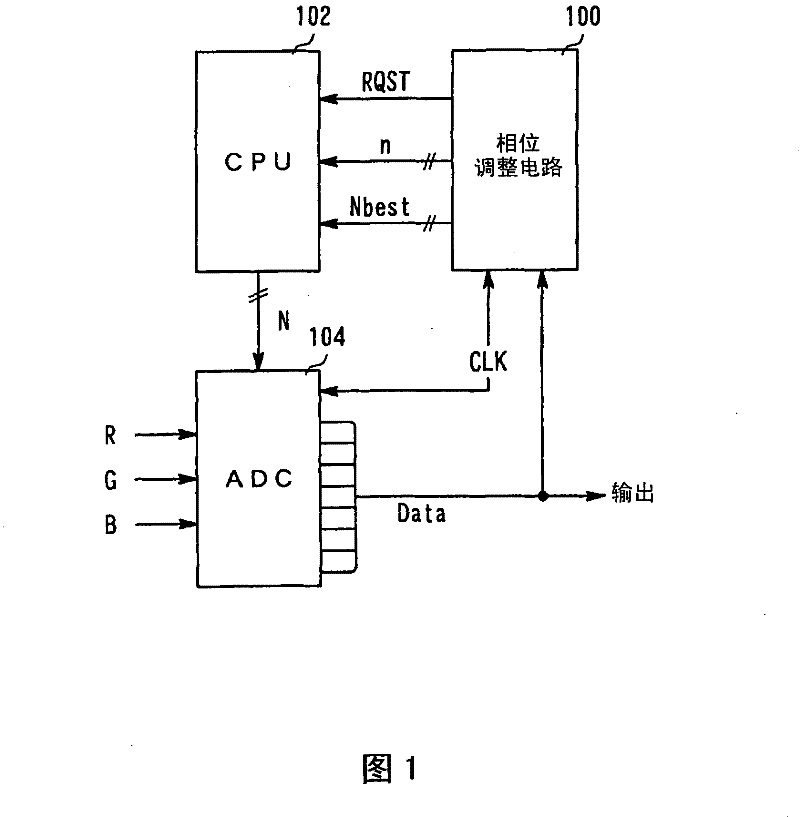
[0022] like figure 1 As shown, the signal processing circuit in the embodiment of the present invention includes a phase adjustment circuit 100 , a control unit (CPU) 102 and an analog / digital circuit (ADC) 104 . In this embodiment, a circuit for digitizing and sampling a video signal is described as an example of a signal processing circuit, but the signal processing circuit is not limited to this.

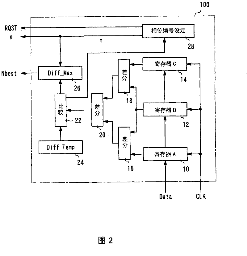
[0023] The phase adjustment circuit 100 receives the input signal Data and the reference clock CLK from the outside, generates a phase change request RQST, a phase number n, and a best phase number Nbest for matching the phases between the input signal Data and the reference clock CLK, and outputs them to CPU102. In order to sample the input signal Data and perform analog / digital conversion in the ADC 104, the phase change request RQST, the phase number n, and the optimum phase number Nbest are used. The operation of the phase adjustment circuit 10...


PUM


Abstract

A signal processing circuit detects the alteration point of the impulse of the input signal, and sets the phase point which has departed for a prescribed phase width relative to the detected alternation point of the impulse of the input signal. Thereby the sampling to the impulse-shaped input signal can be accurately executed.

Description

technical field [0001] The present invention relates to a signal processing circuit for determining sampling timing. Background technique [0002] When sampling a signal that changes periodically, a phase adjustment circuit is used to appropriately set the sampling timing. For example, it is used to set the sampling phase when RGB digital signals obtained from NTSC or PAL television broadcasting are sampled at a predetermined cycle and output. [0003] Figure 7 It is a figure explaining the conventional phase setting method for sampling. The pulse-like input signal SIG that changes periodically is sampled at the rising edge timing of the reference clock CLK whose cycle is half a cycle of the input signal SIG (the timing indicated by a white circle in the figure). At this time, the timing at which the input signal SIG becomes the maximum value and the minimum value in each cycle is a sampling timing, and the phases of the input signal SIG and the reference clock CLK are ma...

Claims


Application Information

Patent Timeline
Patent Type & Authority Patents(China)
IPC IPC(8): H04L7/033H04N5/14H03L7/00
CPCH04L7/0334H03L7/00H03M1/1255H04N5/04G09G5/008H03M1/0863
Inventor 音羽智司材木寿志和田政明
Owner SANYO ELECTRIC CO LTD
Why Eureka
Try Eureka