
Focusing leveling measuring system

A measurement system, focusing and leveling technology, applied in the field of measurement systems, can solve problems such as poor measurement stability, complex system, measurement error, etc., and achieve the effects of improving measurement accuracy, repeatability and stability, and improving resolution.

Active Publication Date: 2010-09-15
SHANGHAI MICRO ELECTRONICS EQUIP (GRP) CO LTD
View PDF6 Cites 0 Cited by
  • Summary
  • Abstract
  • Description
  • Claims
  • Application Information

AI Technical Summary

Problems solved by technology

[0003]With the continuous improvement of the resolution of the projection lithography machine and the continuous decrease of the depth of focus, the measurement accuracy and real-time measurement of the focusing and equalization system in the lithography machine The requirements for the performance of the exposure area are getting higher and higher, and the realization methods of the focusing and leveling measurement system in the form of air pressure sensor and capacitive sensor have been difficult to meet the requirements. For photoelectric measurement systems, such as: photoelectric measurement method based on grating and four-quadrant detector (US Patent US5191200), photoelectric detection method based on slit and four-quadrant detector (US Patent US 6765647B1), based on pinhole and area array CCD (Charge Coupled Device, Charge Coupled Device) photoelectric detection method (US patent US6081614) and PSD (Position Sensitive Device, position sensitive device) based photoelectric measurement method (Chinese patent: 200610117401.0 and Focusing and leveling system using PSDs for the wafer steppers. Proc. SPIE, 1994, 2197: 997-1003.)
[0004] For the above-mentioned existing focusing and leveling measurement systems, their systems are relatively complicated, and except for US patent US5 191200, others are non-differential measurement systems , the measurement stability is relatively poor
And among the above-mentioned existing focusing and leveling measurement systems, the measurement accuracy of other focusing and leveling measurement systems except the photoelectric detection method based on slits and four-quadrant detectors (US Pat. Measurement errors due to the influence of local reflectance unevenness inside a single measurement spot on the object

Method used


Image

  • Focusing leveling measuring system
  • Focusing leveling measuring system
  • Focusing leveling measuring system

Examples


Embodiment Construction

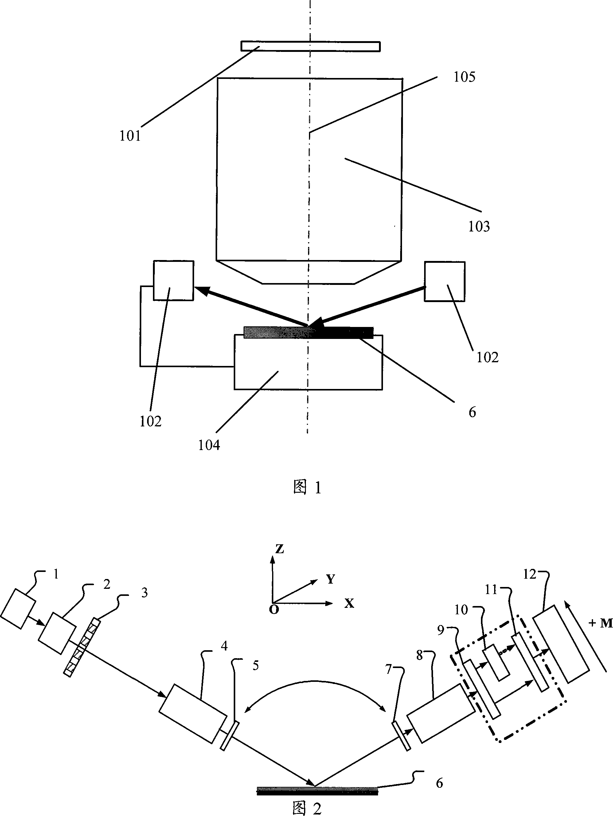
[0027] figure 2 The light emitted by the middle light source module 1 is shaped by the light beam illumination optical module 2 and then irradiated onto the object grating 3; the object grating 3 is imaged by the first imaging module 4 onto the measured silicon wafer (here generally refers to all measured objects) 6 , forming a measurement spot on the upper surface of the silicon wafer 6 . The first imaging module 4 and the second imaging module 8 are imaging systems that are telecentric at least on one side of the silicon wafer 6 . And here the first offset flat plate 5 and the second offset flat plate 7 are mainly used to adjust the measurement zero point of the focusing and leveling measurement system, the first offset flat plate 5 and the second offset flat plate 7 are adjusting At this time, it should be ensured that it can rotate relatively, and the adjustment amount is the same. The detection spot on the upper surface of the silicon wafer 6 is imaged by the second im...


PUM


Abstract

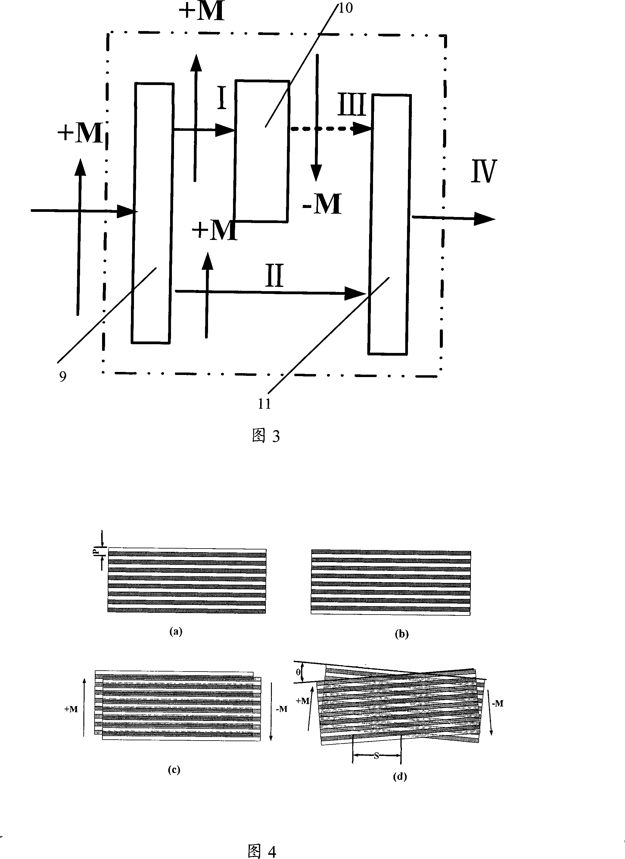
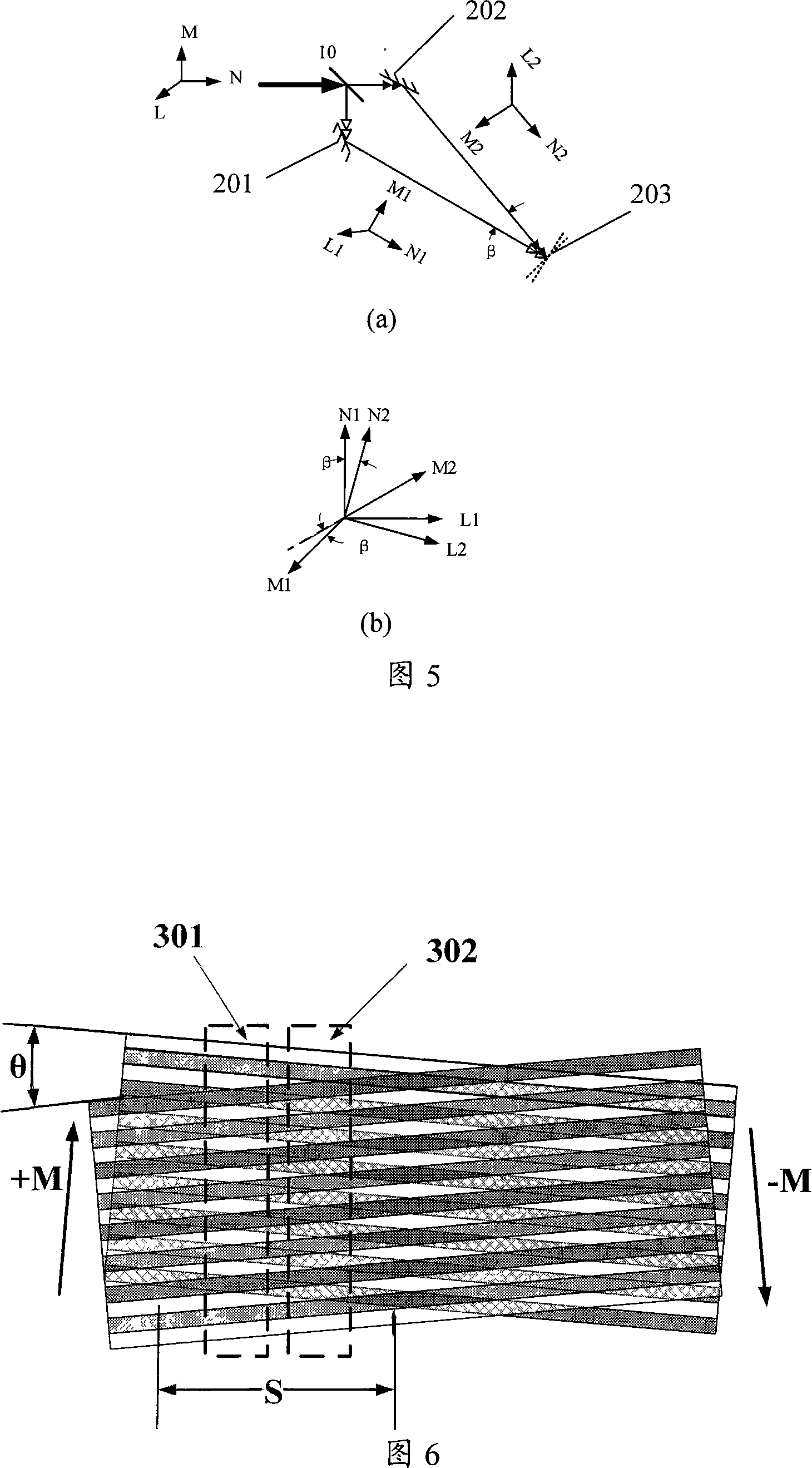
The invention relates to a measuring system of focusing and leveling and consists of a light source module (1), an illuminating optical module (2), an objective grating (3), a first imaging module (4), a first offset panel (5), a measured object (6), a second offset panel (7), a second imaging module (8), a DRC module and still a detecting module (12), wherein, the DRC module consists of a beam splitter (9) and an image inverter (10). Compared with the prior measuring system of focusing and leveling, the invention has higher stability, repeatability and measuring accuracy and can average the measurement error on the measured object (6) caused by an uneven local reflectivity as well as the measurement error caused by the light-intensity variation of the light source and the integral variation of the reflectivity of the measured object. In addition, the invention has the advantages of simple structure and poorer sensibility to the measured object.

Description

technical field [0001] The invention relates to a measurement system, in particular to a measurement system for focusing and leveling a photolithography machine. Background technique [0002] Lithography machine is one of the important equipment for the production of large-scale integrated circuits, such as figure 1 As shown, its function is to transfer the pattern on the mask plate to the silicon wafer 6 (silicon wafer here generally refers to all objects to be exposed, including substrate, coating and photoresist) in a certain proportion. Focusing and leveling measurement system 102 is one of the important subsystems of the lithography machine, it is responsible for measuring the surface position information of the silicon wafer, so that together with the workpiece table system 104 that holds the silicon wafer, the exposed area of ​​the silicon wafer is always under the light. The pattern on the mask plate 101 is ideally transferred to the silicon wafer within the focal d...

Claims


Application Information

Patent Timeline
Patent Type & Authority Patents(China)
IPC IPC(8): G03F9/00G03F7/20
Inventor 关俊
Owner SHANGHAI MICRO ELECTRONICS EQUIP (GRP) CO LTD
Learn More