
Method for producing cutter teeth of spiral bevel gear with spherical involute profile of tooth tapered tooth

A technology of spherical involute and spiral bevel gears, which is applied to gear tooth manufacturing tools, gear tooth manufacturing devices, gear cutting machines, etc., and can solve problems such as inability to obtain spherical involute tooth profiles, increased noise, and manufacturing difficulties

Inactive Publication Date: 2008-04-02
彭福华
View PDF0 Cites 25 Cited by
  • Summary
  • Abstract
  • Description
  • Claims
  • Application Information

AI Technical Summary

Problems solved by technology

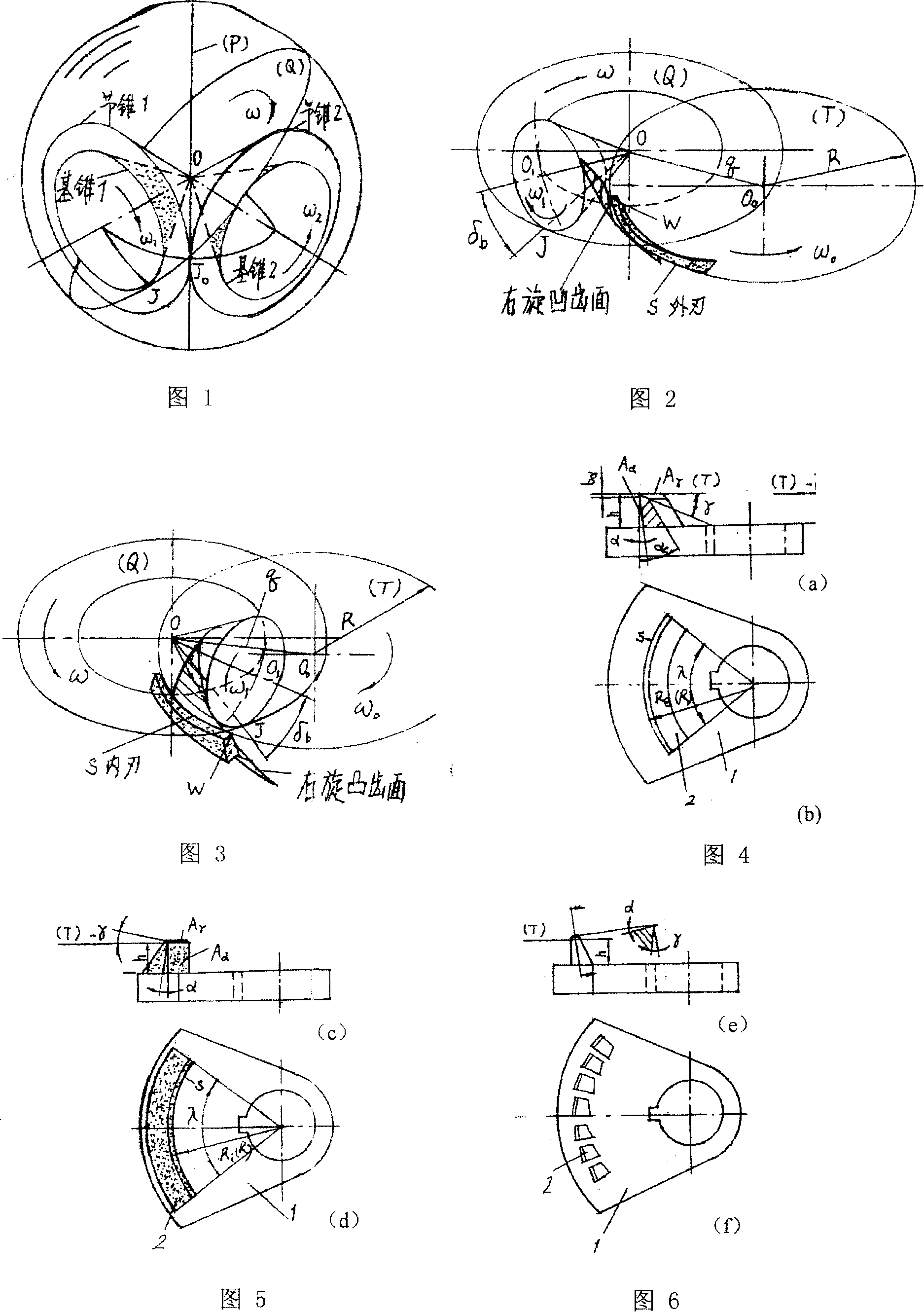
(See Figure 1) However, because the spherical involute cannot be developed in the plane, people have always been limited by the complexity of its calculation and considered it difficult to manufacture, so they resorted to the engineering approximation method, using the back cone to develop the hypothetical equivalent cylindrical gear tooth profile on the plane. Approximate replacement; and the pursuit of simple tool design and manufacture, the conical surface formed by the rotation of the linear blade constitutes the cutting surface of the gear cutter head, which is used to generate the convex and concave tooth surfaces of the milling conjugate (envelope generation method) or form milling (pulling) cutting the tooth surface of the large gear (semi-generated method); the tooth profile of the spiral bevel gear cut in this way is not a spherical involute
What's more, for bevel gears with shrinking teeth, the axes of the cutterheads for milling the paired conjugate tooth surfaces are often inconsistent, resulting in incorrect meshing of the two tooth surfaces, resulting in disadvantages such as poor contact area, increased noise, and reduced strength
For this reason, corrections must be made during design calculations and gear cutting adjustments, which is not only complicated but also requires an inspection machine. Repeated inspections and adjustments will only increase equipment investment and process labor.
It can be said that none of the spiral bevel gears cut by the current gear cutting method can obtain the spherical involute tooth shape, thus losing the unique excellent performance of spherical involute meshing, such as: constant instantaneous speed ratio, influence of transmission angle change Contact zone insensitivity, contact zone can be precisely determined, machined gears are interchangeable

Method used


Image

  • Method for producing cutter teeth of spiral bevel gear with spherical involute profile of tooth tapered tooth
  • Method for producing cutter teeth of spiral bevel gear with spherical involute profile of tooth tapered tooth
  • Method for producing cutter teeth of spiral bevel gear with spherical involute profile of tooth tapered tooth

Examples


Embodiment

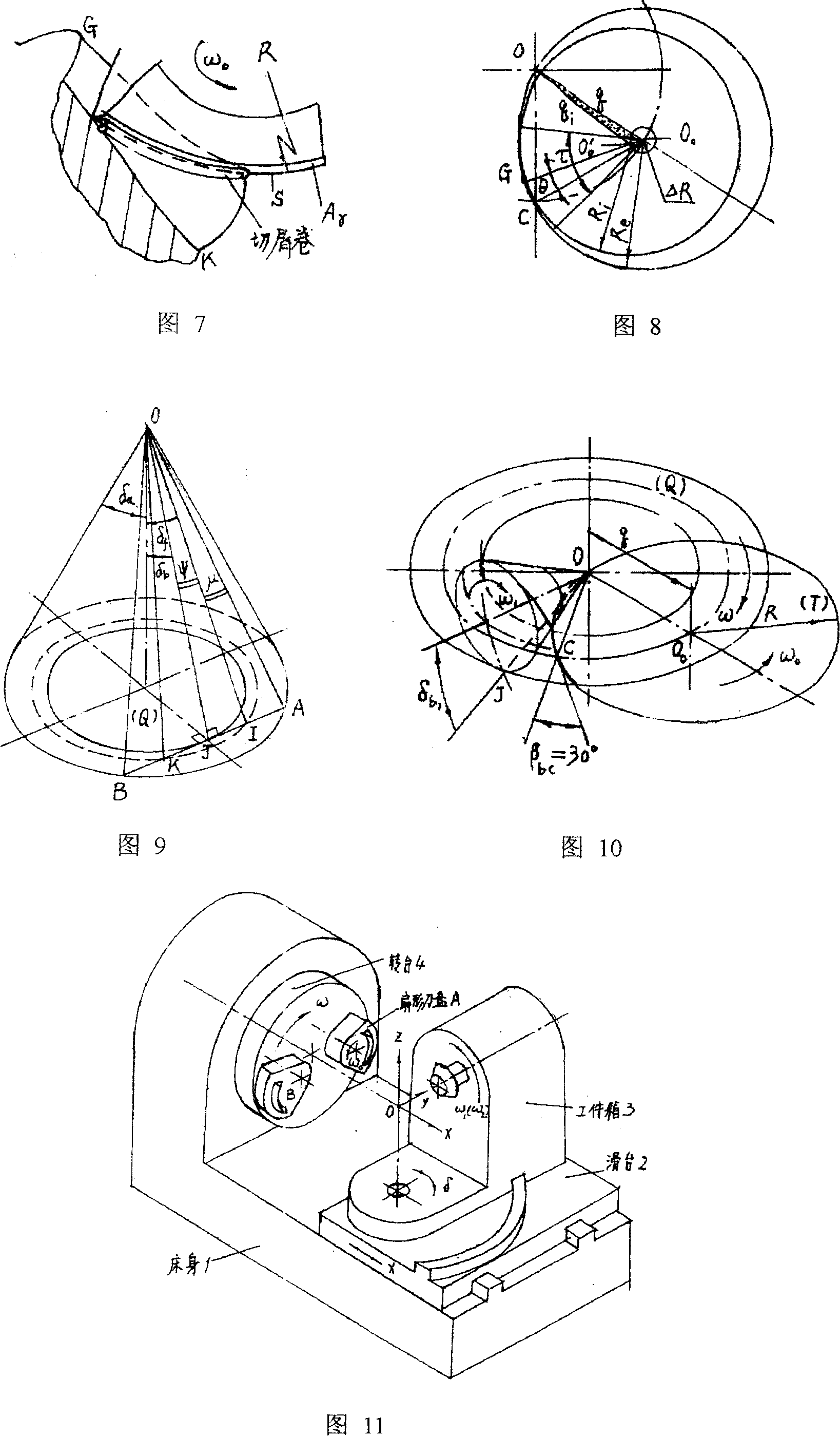
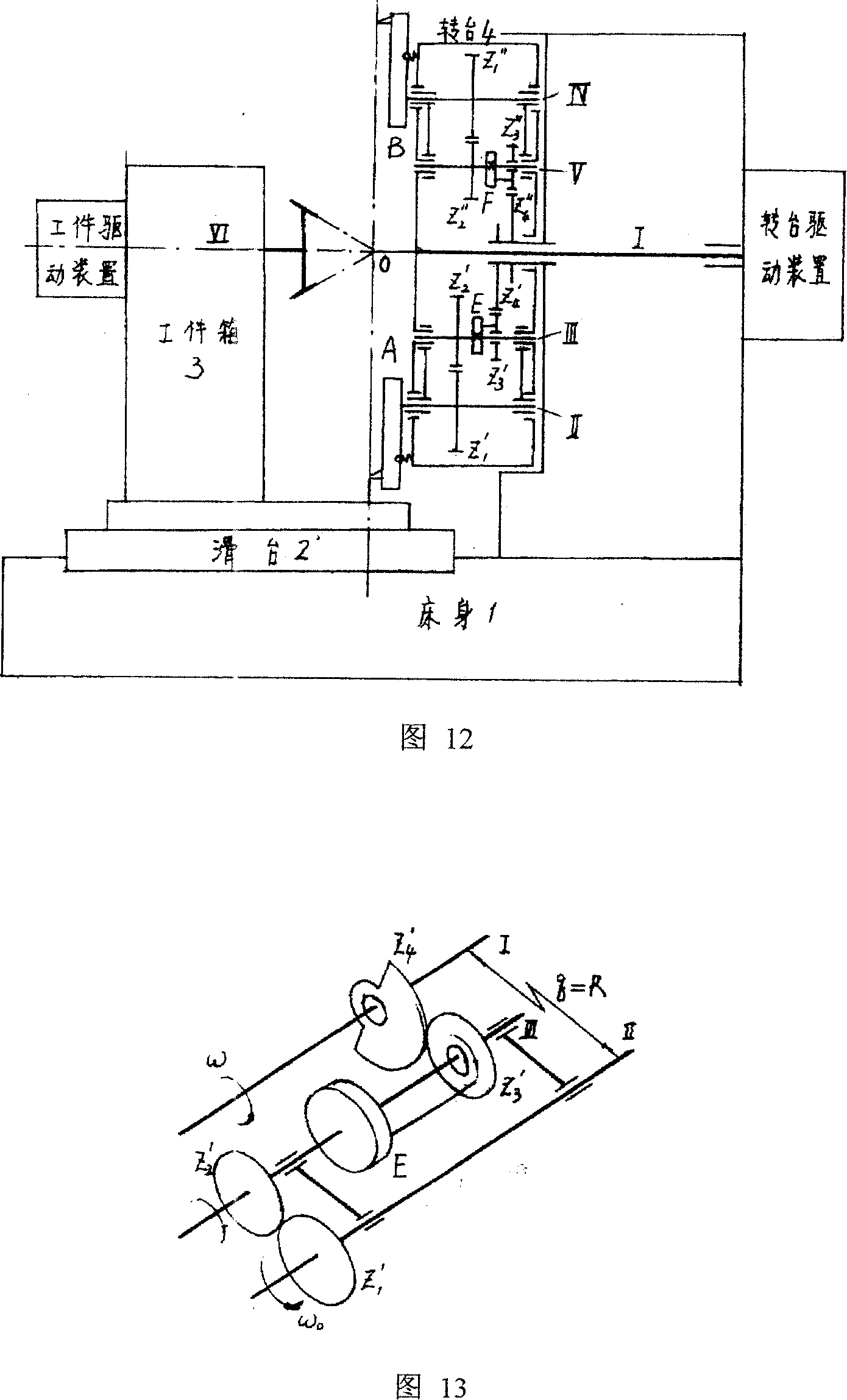
[0057] Press R=q and Z Q * Definite principle implements the machine tool of gear cutting method of the present invention to show in accompanying drawing 11,12,13, and lathe layout is the same as traditional layout, by bed 1, slide table 2, workpiece box 3, turntable 4, fan-shaped outer edge cutterhead A, fan-shaped interior The blade cutter disc B and other components, the workpiece box 3 rotates around Z, satisfying δ b The adjustment; the sliding table 2 is adjusted along the X axis to meet the tangent between the base cone and the (Q, T) plane; when the rough milling cutter is used to mill the tooth groove, the full tooth height can be gradually milled according to the X axis direction feed In order to reduce the load of the milling cutter teeth; the gear blank axis VI is given ω by the workpiece driving device 1 , ω 2 The movement of the turntable is composed of a planetary gear train, where Z' 4 ,Z" 4 It is a sun gear (fixed when cutting teeth, loosen to adjust the ...


PUM


Abstract

The invention relates to a gear cutting method for manufacture of spiral bevel gear with spherical involute tooth profile shrinkage tooth which is the gear cutting method that an arc-shaped cutting edge skiving cutterhead with turning radius of R on an end surface (T) is adopted for turning of spherical involute tooth profile and the shrinkage tooth is adopted to manufacture the tooth surface of the spiral bevel gear. When in cutting, a tooth casting is tangental to spherical large round plane (Q) represented by machine tool shaking station turning plane and maintains pure rolling according to base cone, rotating speed of every shaft of the machine tool is set up according to following speed ratio relations: when rotating speed of the shaking station is omega, rotating speed of the tooth casting is (1) type, wherein, ZQ is hypothetical tooth number of the shaking station, rotating speed of a cutterheadshaft is (2) type, and omega is opposite to the direction of omega 0; skiving cutterhead knife edge S is tangental to processed tooth surface and tooth surface fine turning process without generation of undercut is finished in the state of large bevel turning. Engaging quality of the cutting gear manufactured with the method is improved, with transient speed ratio constancy and insensitivity of influence of contacting area by transmission included angle alteration, moreover, the gear processed with the method can be exchanged and the invention simplifies the design of the gear and machine tool.

Description

technical field [0001] The invention relates to the design and gear cutting processing technology of spiral bevel gears, in particular to a tooth surface processing method for manufacturing spiral bevel gears with spherical involute tooth profile shrinking teeth. Background technique [0002] Bevel gears are important transmission elements for transmitting the motion and power of intersecting shafts, among which Gleason (GLEASON) shrinking tooth spiral bevel gears with a history of more than 100 years are widely used. As we all know, in theory, for a pair of bevel gears with correct conjugate transmission, the cone tops of the two gears are at the same point, and only the points on the tooth surface that are equidistant from the cone tops can contact each other, that is, all points on the conjugate tooth profile must be on the same spherical surface Therefore, the profile of the tooth surface of the bevel gear should be a spherical involute. (See Figure 1) However, because ...

Claims


Application Information

Patent Timeline
Patent Type & Authority Applications(China)
IPC IPC(8): B23F9/00B23F21/00B23F23/12B23F23/02B23C3/28
CPCB23F9/10
Inventor 彭福华
Owner 彭福华
Learn More