
Method and system for optimizing a finite element mesh

a mesh and finite element technology, applied in the field of methods and systems for optimizing finite element meshes, can solve the problem that the method does not necessarily generate elements having a better overall quality, and achieve the effect of improving the overall improving the quality of the mesh, and improving the quality scor

Inactive Publication Date: 2006-02-09
FORD MOTOR CO
View PDF18 Cites 1 Cited by
  • Summary
  • Abstract
  • Description
  • Claims
  • Application Information

AI Technical Summary

Benefits of technology

The present invention is a computer-implemented method and system for evaluating and optimizing finite element meshes. It allows for the simultaneous evaluation and optimization of multiple quality attributes, resulting in a better overall quality of the mesh compared to prior art methods. The system receives a finite element mesh in electronic format and calculates a quality score for each element based on two or more quality attributes. It also considers multiple potential substitute elements for the original element(s) to improve the overall quality of the mesh. The quality score of each substitute element is compared to the original element's score, and if a substitute element has a better score, it replaces the original element. The method and system can also be used to replace certain elements in a finite element mesh to improve its quality. Overall, the invention provides a more efficient and effective way to evaluate and optimize finite element meshes.

Problems solved by technology

Although the paver cleanup method may be effective at controlling / correcting node valence, the method does not necessarily generate elements having a better overall quality.

Method used


Image

  • Method and system for optimizing a finite element mesh
  • Method and system for optimizing a finite element mesh
  • Method and system for optimizing a finite element mesh

Examples


Embodiment Construction

Method Overview

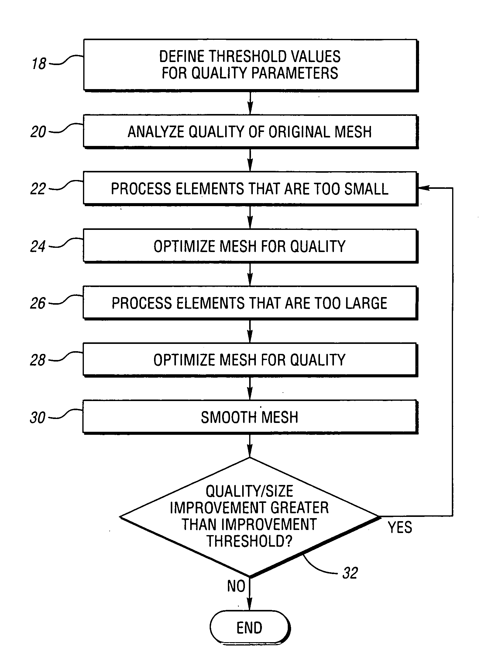
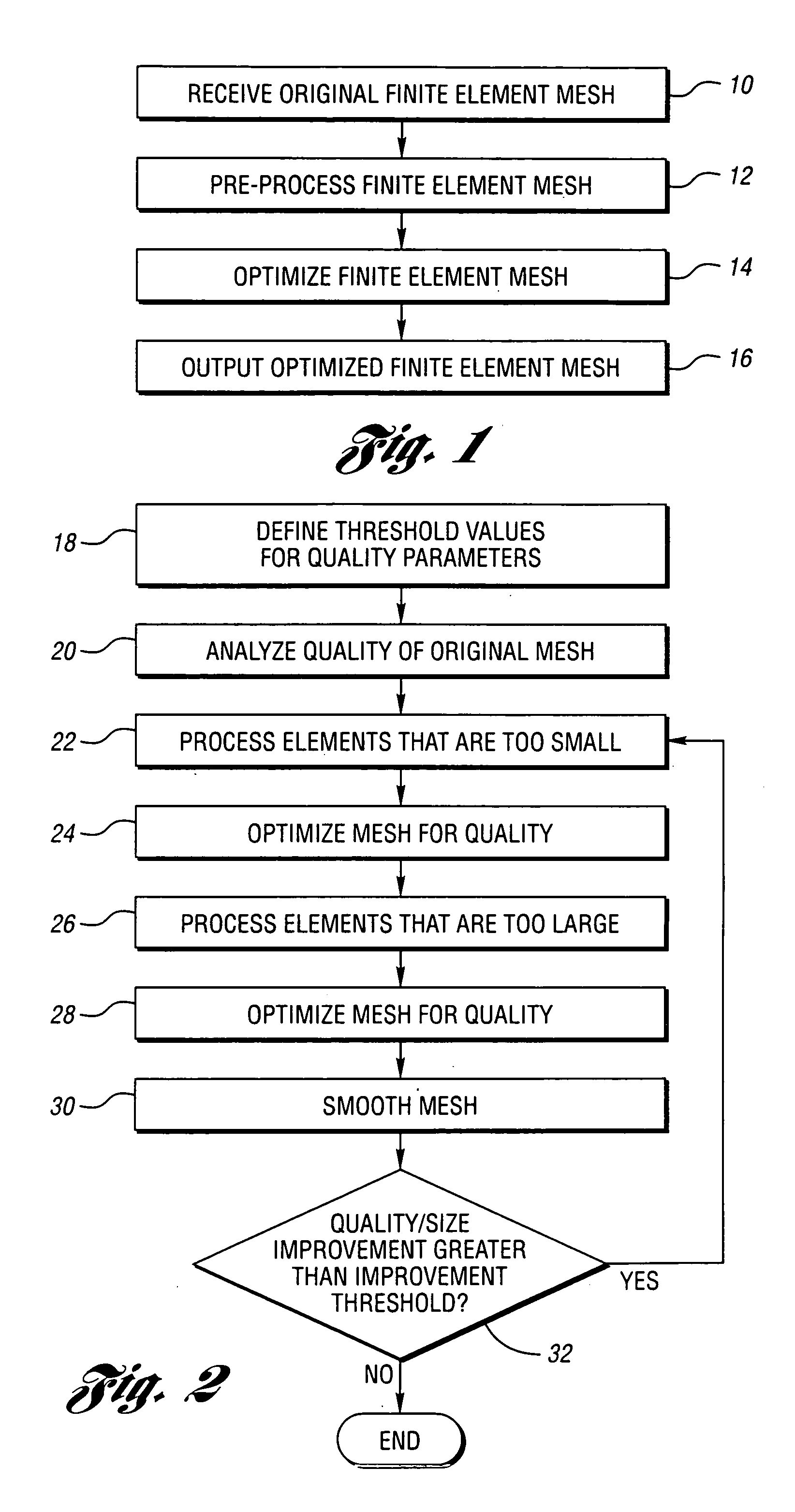
[0027]FIG. 1 is a block flow diagram illustrating a preferred methodology for implementing the present invention. Notably, the content and arrangement of items illustrated in FIG. 1 may be rearranged or adapted to best fit a particular implementation of the present invention. As represented in block 10, an original finite element mesh is received in an electronic format. Electronic file formats for finite element meshes include NASTRAN and RADIOSS. As represented in block 12, the finite element mesh is pre-processed in a computer-automated fashion. This aspect of the present invention is described in greater detail below. As represented in block 14, the mesh is optimized utilizing a computer-implemented optimization algorithm described in greater detail below. As represented in block 16, the optimized mesh is output in an electronic format.

Mesh Preprocessing

[0028] In accordance with a preferred embodiment of the present invention, original mesh preprocessing or b...


PUM


Abstract

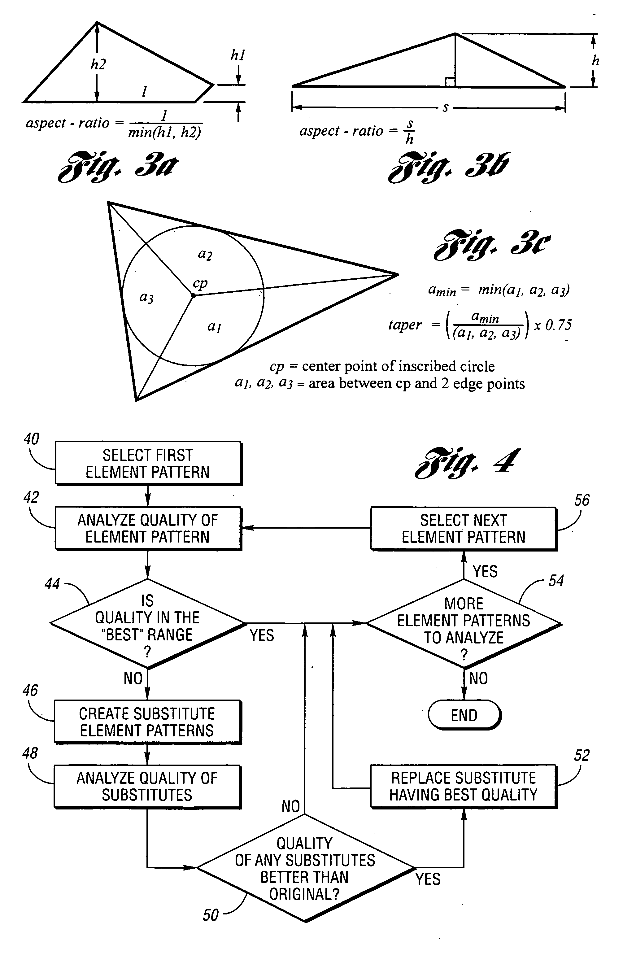
Computer-implemented method and system for optimizing a finite element mesh. Computing devices are configured to calculate a quality score for at least one original element in a finite element mesh based upon two or more quality attributes simultaneously. A quality score for at least one substitute element for the original element is calculated based upon the two or more quality attributes. If one or more substitute element(s) have a quality score that is better than the quality score of the original element(s), the original element(s) is / are replaced with the substitute element(s) having the best quality score. A quality score may be calculated for each of a plurality of combinations of one or more substitute elements. Input may be provided specifying at least one quality threshold value for comparing the two or more element quality parameters (skew, warp, aspect ratio, etc.).

Description

CROSS-REFERENCE TO RELATED APPLICATIONS [0001] This application is a continuation of U.S. application Ser. No. 10 / 248,115 filed Dec. 19, 2002.BACKGROUND OF THE INVENTION [0002] 1. Field of the Invention [0003] The present invention relates generally to methods and systems for cleaning or otherwise enhancing the quality of finite element meshes. [0004] 2. Background Art [0005] One method for cleaning a finite element mesh is known as the paver cleanup method developed at Sandia National Laboratories. This method focuses on the valence of finite element mesh elements—the number of element edges that include a node or the number of mesh elements around a node. Because the paver mesh comprises all quad elements, the goal of the cleanup algorithm is to generate as many nodes as possible having a valence of 4. [0006] The first step in the paver cleanup method is, for each node in the mesh, to compute the node valence and the valence of all nodes in the ring around it. This series of numbe...

Claims


Application Information

Patent Timeline
Patent Type & Authority Applications(United States)
IPC IPC(8): G06T17/20G06T15/30
CPCG06T17/205G06T17/20
Inventor WOLLNY, MARTIN R.KINNEY, PAUL RICHARD
Owner FORD MOTOR CO
Learn More