Electric ignition pipe for gas generator and its ignition method
A technology of gas generators and electric ignition tubes, which is applied to belt tighteners, vehicle components, pedestrian/passenger safety arrangements, etc., and can solve the problem of difficult guarantee of safety and reliability, failure of airbags or seat belt pretensioners , complex manufacturing process and other issues, to achieve high reliability, reduce the probability of misfired ignition, and simple production process
- Summary
- Abstract
- Description
- Claims
- Application Information
AI Technical Summary
Problems solved by technology
Method used
Image

Examples
Embodiment 1
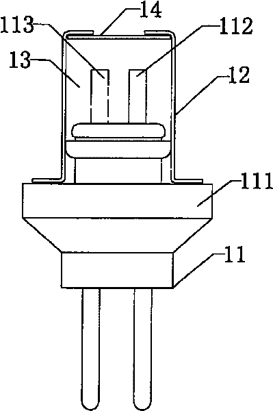
[0023] see image 3 , the electric ignition tube of the present invention includes an electrode plug 11, and the electrode plug 11 is composed of a first core electrode 112, a second core electrode 113 and an insulating base 111. It also includes a housing 12, which is provided with an opening, and The opening of the housing 12 is provided with an upper cover 14, and the surface of the seal between the opening of the housing 12 and the upper cover 14 is coated with lacquer; the housing 12 is sleeved on the insulating base 111 of the electrode plug 11, and the The first core electrode 112 and the second core electrode 113 of the electrode plug 11 are placed in the inner cavity of the housing 12, and are sealed with shellac paint at the contact between the housing 12 and the electrode plug 11. The upper cover 14 is soft insulation Inert material, preferably a phenolic resin sheet. The inner cavity of the housing 12 is tightly pressed with a conductive agent 13; the conductive ag...
Embodiment 2
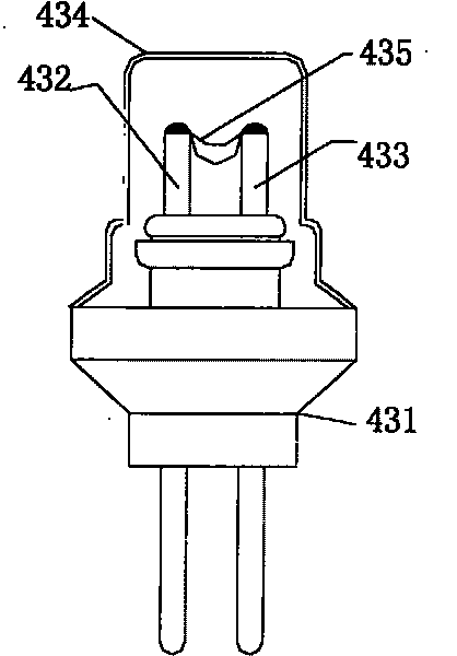
[0025] see Figure 4 , the electric ignition tube of the present invention includes an electrode plug 21, the electrode plug 21 is composed of a first core electrode 212 and an insulating base 211; it also includes a housing 22, an opening is provided on the housing 22, and an upper cover is provided at the opening of the housing sheet 24, and coat the surface of the seal between the opening of the casing 22 and the upper cover sheet 24 with lacquer; the casing 22 is set on the insulating base 211 of the electrode plug 21, and the Contacts are sealed with shellac. The upper cover sheet 24 is a soft insulating and inert material, preferably a phenolic resin sheet. The conductive agent 23 is tightly pressed into the inner cavity of the housing 22; the conductive agent 23 is made by uniformly doping and mixing conductive substances in common ignition powder; the conductive substance is preferably powdered graphite. The proportion of the conductive substance in the conductive ag...
Embodiment 3
[0027] Please combine Figure 5 , Image 6 , Figure 7 As shown, the electric ignition tube of the present invention includes an electrode plug, and the electrode plug is composed of a first core electrode 312, a second core electrode 313 and an insulating base 311; it also includes a casing 32 and a cover sheet, and the casing 32 is insulated Sleeve, the two sides of the insulating sleeve are provided with small protrusions, and the cover sheet includes two pieces of left cover sheet 35 and right cover sheet 36, such as Figure 8 As shown, there are deep rice-shaped grooves 351 on it, and hooks are provided at both ends of the cover; the hooks of the cover cooperate with the small protrusions of the insulating sleeve and are sealed on both sides of the insulating sleeve. , and apply nitrocellulose varnish to seal the seal. The left cover sheet 35 and the right cover sheet 36 are conductive materials, preferably copper cover sheets. And the hooks at one end of the two cove...
PUM
 Abstract
Description
Claims
Application Information
 - R&D
- Intellectual Property
- Life Sciences
- Materials
- Tech Scout
- Unparalleled Data Quality
- Higher Quality Content
- 60% Fewer Hallucinations
Browse by: Latest US Patents, China's latest patents, Technical Efficacy Thesaurus, Application Domain, Technology Topic, Popular Technical Reports.
© 2025 PatSnap. All rights reserved.Legal|Privacy policy|Modern Slavery Act Transparency Statement|Sitemap|About US| Contact US: help@patsnap.com