
Fuel alcohol dewatering apparatus and process

A dehydration device, fuel ethanol technology, applied in the chemical industry, sustainable manufacturing/processing, preparation of organic compounds, etc., can solve the problem of high energy consumption for solvent regeneration, achieve low energy consumption, high overall efficiency, and recycling rate high effect

Inactive Publication Date: 2007-12-19
GUANGDONG ZHONGKE TIANYUAN NEW ENERGY SCI & TECH
View PDF0 Cites 17 Cited by
  • Summary
  • Abstract
  • Description
  • Claims
  • Application Information

AI Technical Summary

Problems solved by technology

However, solvent regeneration consumes more energy

Method used


Image

  • Fuel alcohol dewatering apparatus and process

Examples


Embodiment

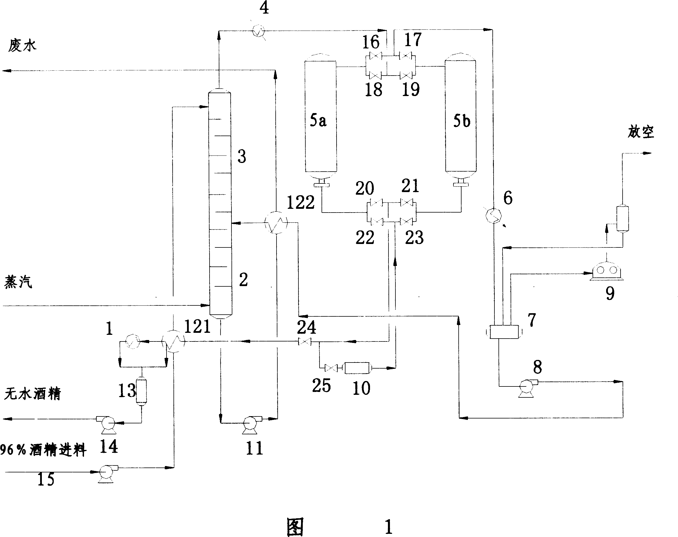
[0028] Embodiment: as shown in Figure 1, the fuel ethanol dehydration device with an annual output of 50,000 tons comprises a rectifying tower 3 and a stripping tower 2 arranged in series up and down, a first molecular sieve 5A and a second molecular sieve 5B arranged in parallel, a superheated 4, product cooler 1, feed preheater 121, feed pump 15, light wine tank 7, regeneration condenser 6, light wine pump 8, regeneration regulator wastewater pump 11, light wine preheater 122, middle The tank 13, the product pump 14 and the vacuum pump 9, wherein the top of the first molecular sieve 5A and the second molecular sieve 5B pass through the first inlet valve 18 and the second inlet valve 19 and the first regeneration outlet valve 16 and the first regeneration outlet valve 16 and the second inlet valve respectively arranged in parallel in series. The two regeneration outlet valves 17 communicate, and the bottom of the first molecular sieve 5A and the second molecular sieve 5B pass ...


PUM


Abstract

The fuel alcohol dewatering apparatus a rectification tower and a stripping tower connected serially, two parallel molecular sieves with valves in the inlets and the outlets, an overheater, a product cooler, a material preheater, a feeding pump, a waste water pump and a vacuum pump. The present invention has low power consumption, high energy recovering rate, no environmental pollution and high production efficiency.

Description

technical field [0001] The invention relates to an ethanol dehydration device and a process thereof, in particular to a dehydration device and a process for directly producing fuel ethanol after distillation. technical background [0002] With the shortage of global oil resources and the increase of uncertain factors, renewable energy represented by fuel ethanol has attracted more and more attention. Ethanol can be produced continuously through the fermentation and distillation of grains, tubers and sugary raw materials. However, the concentration of ethanol produced by distillation shall not exceed 96% (v / v), and the ethanol content of fuel ethanol in fuel ethanol used as an effective additive for gasoline and diesel must not be less than 99.5% (w / w). The method of ethanol dehydration There are roughly the following types: [0003] (1) Chemical reaction dehydration, one of which is the Meiek method. Quicklime and calcium chloride are used as dehydrating agents, and 0.55 k...

Claims


Application Information

Patent Timeline
Patent Type & Authority Applications(China)
IPC IPC(8): C07C31/08C07C29/80
CPCY02P20/10Y02P20/50
Inventor 陈勇唐兆兴姜新春余伟俊陈宪笙徐晓东
Owner GUANGDONG ZHONGKE TIANYUAN NEW ENERGY SCI & TECH
Learn More