LED light-emitting component

A technology of light-emitting elements and light-emitting wafers, applied to semiconductor devices of light-emitting elements, optical elements for changing the spectral characteristics of emitted light, light sources, etc., can solve the problem of changing spatial light intensity distribution and color temperature Ra value, changing color parameters, Edge color cast and other problems, to avoid high temperature heating, uniform light color rendering, reduced light attenuation

Active Publication Date: 2007-12-05
DAJIN ORIENT LIGHTING SHENZHEN
View PDF1 Cites 14 Cited by
  • Summary
  • Abstract
  • Description
  • Claims
  • Application Information

AI Technical Summary

Problems solved by technology

[0008] The purpose of the present invention is to propose a method for improving the distribution of fluorescent powder on the LED surface LED light-emitting element, to solve the problem of affecting light efficiency due to the use of coating methods, changing color parameters, changing spatial light intensity distribution and color temperature Ra value, and serious edge problems. Problems such as color cast

Method used


Image

  • LED light-emitting component

Examples


Embodiment 1

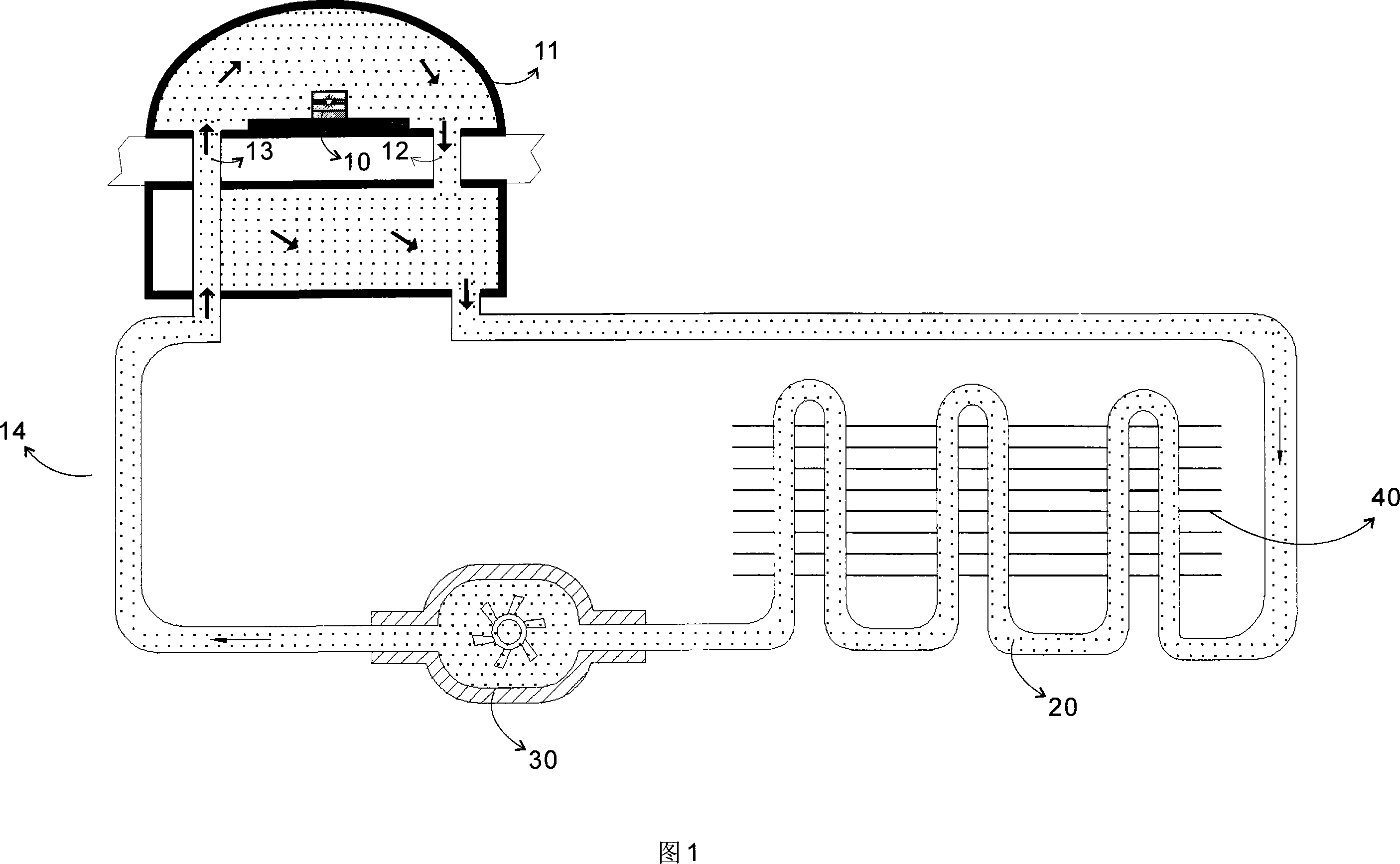
[0017] As shown in FIG. 1 , an LED light-emitting element is provided with an LED light-emitting chip 10 mounted on a metal substrate in a transparent cover 11 . The transparent cover 11 preferably adopts an outer contour with optical characteristics. The transparent cover 11 is provided with flow liquid circulation inlets and outlets 12, 13, and the flow liquid circulation inlets and outlets 12, 13 are preferably arranged on the bottom surface of the transparent cover 11 to form a sealed space. Connect a liquid cooling circulation cooling device 14 at the inlet and outlet 12 and 13 of the flowing liquid circulation, fill the transparent cover 11 with liquid through the liquid cooling circulation cooling device 14, and make the liquid cover the LED light emitting chip 10 surface. Phosphor powder is added to the liquid, so that the phosphor powder is uniformly dispersed in the liquid on the surface of the LED light-emitting chip 10 , wherein the flowing liquid containing the ph...


PUM


Abstract

This invention discloses a sort of LED flaring element which adopt the complex flaring technique of fluorescent powder, it makes the LED flaring wafer of metal base plate embark locate in a transparent cover, the transparent cover is full of liquid in order that the liquid can submerge the whole surface of LED flaring wafer and it accession fluorescent powder in the liquid, so the fluorescent powder equably disperse in the liquid of the surface of LED flaring wafer. This invention ameliorates the method of the distribution of the external fluorescent powder, it effectively avoids the phenomenon that the fluorescent powder in the surface of LED flaring wafer heat up in the high temperature and reduces the aging of the fluorescent powder and reduce the light attenuation greatly.

Description

technical field [0001] The invention relates to an LED light-emitting element adopting phosphor powder composite light-emitting technology. Background technique [0002] In 1996, Japan's Nichia Chemical discovered that yellow-emitting yttrium-aluminum-garnet (YAG) phosphors combined with blue light-emitting diodes could be used as a white light source. Using the blue LED as the basic light source, a part of the blue light emitted by the blue LED is used to excite the phosphor, so that the phosphor emits yellow-green light or red light and green light, and the other part of the blue light is transmitted, and the yellow-green light or red light of the phosphor is transmitted. White light is composed of green light and transmitted blue light. [0003] At present, people are also developing special phosphors for purple and ultraviolet series. The emission wavelength of this kind of phosphor is 370-420nm. Using the method of coating, this kind of phosphor can also produce white ...

Claims


Application Information

Patent Timeline
Patent Type & Authority Applications(China)
IPC IPC(8): F21V9/12F21V3/02F21Y101/02F21Y115/10
Inventor 朱建钦
Owner DAJIN ORIENT LIGHTING SHENZHEN
Why Eureka
Try Eureka