
Linear high frequency antenna

A wire antenna and ultra-high frequency technology, applied in the field of UHF radio engineering, can solve the problems of low power capacity, limited bandwidth, high input loss, etc., and achieve the effects of improving electrical performance, simplifying structural design, and reducing size

Active Publication Date: 2007-11-07
FEDERAL STATE UNITARY ENTERPRISE STATE MOSCOW PLANT SALYUT
View PDF1 Cites 1 Cited by
  • Summary
  • Abstract
  • Description
  • Claims
  • Application Information

AI Technical Summary

Problems solved by technology

The slot waveguide antenna with inclined slots on the narrow side of the waveguide has a simple structure, but has many disadvantages: limited bandwidth (10%); there is resonance caused by the dispersion characteristics of the waveguide and the series connection of the slots; the average coupling coefficient does not exceed 10dB at most, and the relative Low efficiency (80-90%) and high side lobe level of the antenna pattern (especially when the number of slots is small) when adjacent slots have relative tilt angles; undesired underscan
[0006] These antennas have many disadvantages: complex shape, high input loss, and low power handling

Method used


Image

  • Linear high frequency antenna
  • Linear high frequency antenna
  • Linear high frequency antenna

Examples


Embodiment Construction

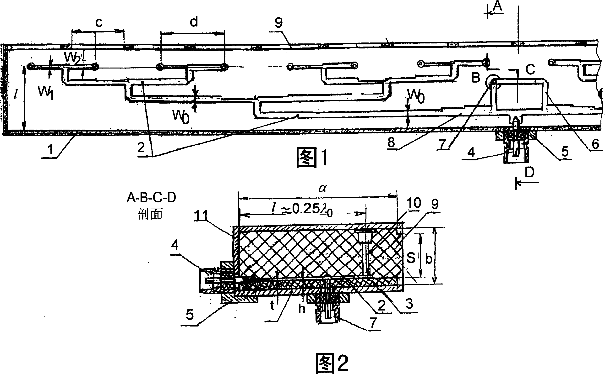
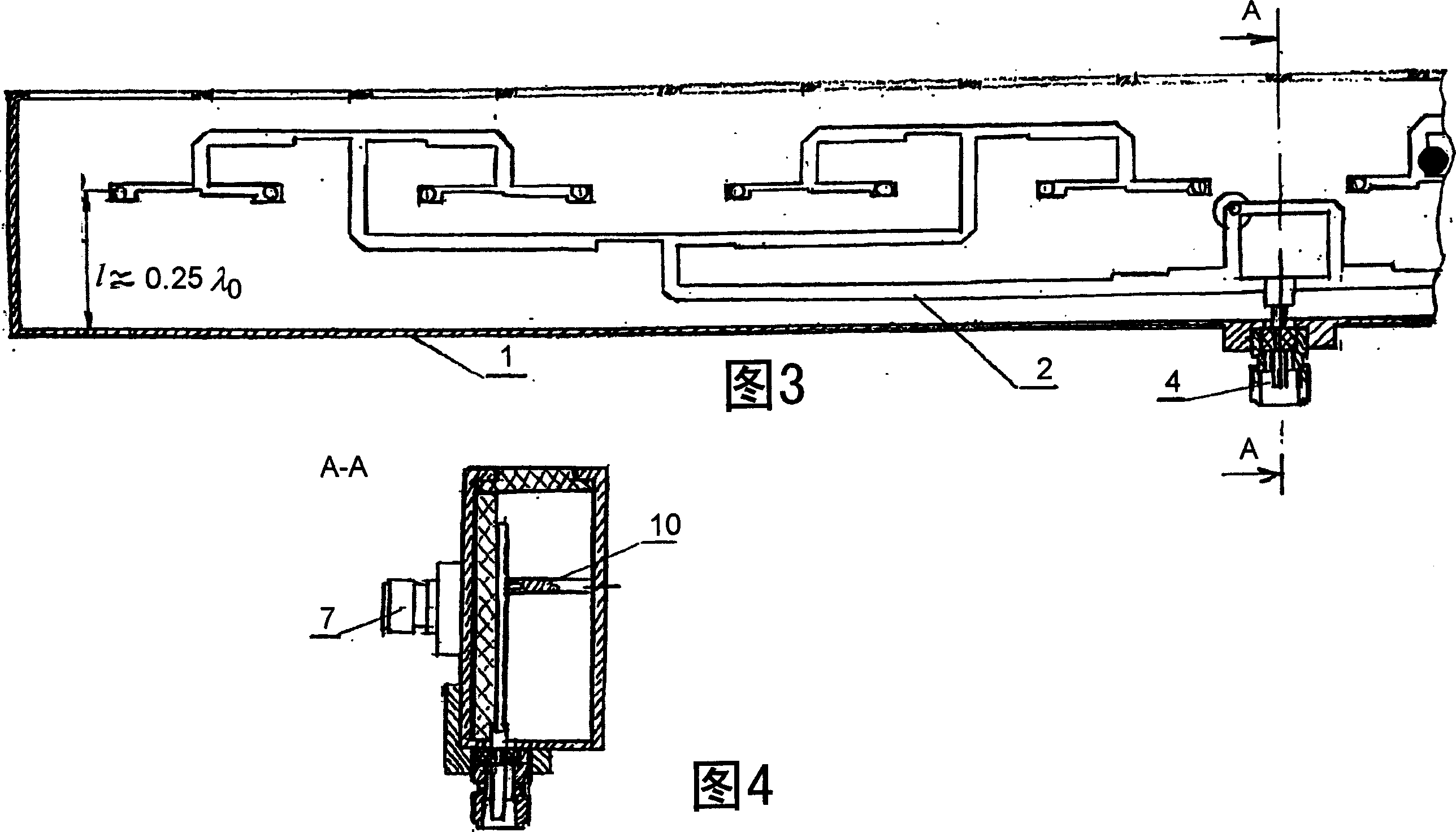
[0013] The present invention (see Figures 1 and 2) consists of a rectangular tube 1 (not necessarily a waveguide), a multi-channel power splitter 2 fabricated on an asymmetric stripline with a dielectric substrate 3 (made of e.g. foam), placed On the wide side inside the rectangular tube 1.

[0014] The conductors of the multi-channel power splitter 2 are made of thin sheets (1-2 mm), such as hard aluminum alloys. Compared with printed conductors, this can reduce loss and increase power capacity. The economics of doing this are obvious, since with today's computer technology it is possible to produce slightly complex structures at low cost.

[0015] The input coaxial connector 4 is located at one side of the narrow side of the rectangular tube, and is fixed on the narrow side with a seat 5 .

[0016] To receive the differential channels with this wire antenna, a "hybrid loop" type bridge arrangement 6 is connected to the input of the multichannel splitter 2 . The differentia...


PUM


Abstract

Implementing an investment strategy to be executed for an individual investor in a single financial contract, covering a plurality of assets. The assets underlying the financial contract are managed using at least a tactical and a strategic asset allocation model. Information regarding risk tolerance, investing time horizon and investment needs of the investor is used to determine (i) a combination of tactical and strategic asset allocation models to manage the assets in the contract; and (ii) a relative percentage of allocation of the assets between the tactical and strategic asset allocation models.

Description

technical field [0001] The invention relates to UHF radio engineering and can be applied to the development of centerline antennas and flat panel antenna arrays for radiolocation systems (eg warning radar). Background technique [0002] Slot waveguide antenna widely used in radiolocation ("VHF antennas" by G.Z. Izenberg et al., Part II, pp. 177-205, "Communication" publishing house, M., 1997; Russian patents SU 1746444, RU 2206157) It is a rectangular waveguide with slots periodically distributed on the narrow side or broad side. The slot waveguide antenna with inclined slots on the narrow side of the waveguide has a simple structure, but has many disadvantages: limited bandwidth (10%); there is resonance caused by the dispersion characteristics of the waveguide and the series connection of the slots; the average coupling coefficient does not exceed 10dB at most, and the relative Low efficiency (80-90%) and high side lobe level of the antenna pattern (especially when the nu...

Claims


Application Information

Patent Timeline
IPC IPC(8): H01Q13/22
CPCH01Q21/0075H01Q13/22H01Q21/08
Inventor 尼古拉·丹尼洛维奇·博罗金阿列克谢·伊万诺维奇·涅莫利亚耶夫
Owner FEDERAL STATE UNITARY ENTERPRISE STATE MOSCOW PLANT SALYUT
Learn More