
Ferrite material, ferrite film formed thereof, and radio frequency identification tag with ferrite film

A ferrite material and ferrite film technology, applied in the field of radio frequency identification tags, can solve the problem that composite materials are not effective

Active Publication Date: 2007-10-17
TOKIN CORP
View PDF2 Cites 4 Cited by
  • Summary
  • Abstract
  • Description
  • Claims
  • Application Information

AI Technical Summary

Problems solved by technology

Among them, the composite material is not effective in the carrier frequency band of 900MHz or 2.45GHz

Method used


Image

  • Ferrite material, ferrite film formed thereof, and radio frequency identification tag with ferrite film
  • Ferrite material, ferrite film formed thereof, and radio frequency identification tag with ferrite film
  • Ferrite material, ferrite film formed thereof, and radio frequency identification tag with ferrite film

Examples


Embodiment Construction

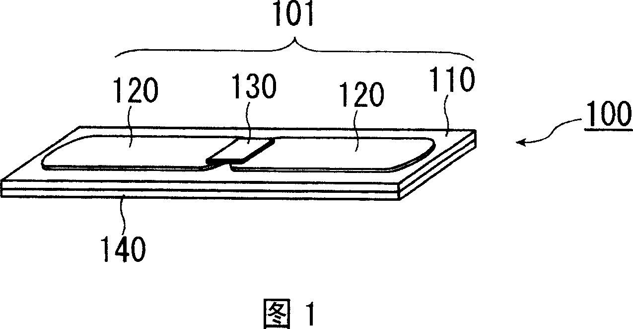
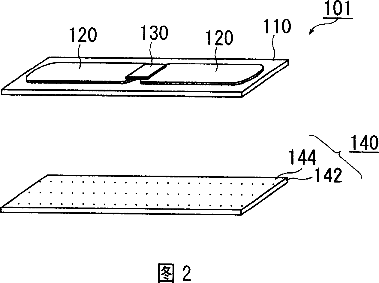
[0021] Referring to FIGS. 1 and 2 , an RFID tag 100 according to an embodiment of the present invention includes a main member 101 and a ferrite sheet 140 glued to the bottom surface of the main member 101 . The illustrated main member 101 includes a label base 110 . In this embodiment, the label substrate 110 is made of polyethylene terephthalate (PET). On the top surface of the label substrate 110, a plane antenna conductor 120 is formed by printing. On the center of the antenna wire 120, an integrated circuit (IC) chip is mounted.

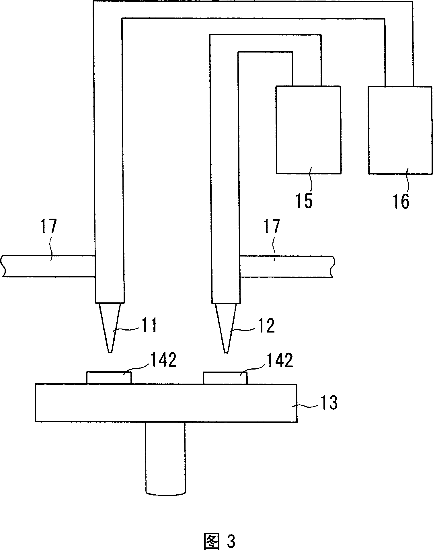
[0022] As shown in FIG. 2, the illustrated ferrite sheet 140 includes a supporter sheet made of polyimide on the surface on which a ferrite thin film 144 is directly formed by a ferrite plating method. 142. The ferrite plating method is as disclosed in USP 4,477,319, the contents of which are hereby incorporated by reference in their entirety. The ferrite electroplating method of the present embodiment comprises the steps of: preparing a spe...


PUM

PropertyMeasurementUnit
thicknessaaaaaaaaaa
thicknessaaaaaaaaaa
aspect ratioaaaaaaaaaa

Abstract

A ferrite material is disclosed, consisting of an oxide metal composition, the metal composition having the formula of FeaNibZncCod, where: a+b+c+d=3.0; 2.1<=a<=2.7; 0<=b<=0.4; 0<=c<=0.4; and 0.1<=d<=0.5. A ferrite film is made of the ferrite material. Preferably, the ferrite film is formed by a ferrite plating method to have a thickness of 30 mum or less and an aspect ratio of 30 or more. The ferrite film is arranged or provided in the vicinity of an antenna conductor of a radio frequency identification tag. The ferrite film may be in direct contact with the antenna conductor.

Description

technical field [0001] The present invention relates to a ferrite material, a ferrite film made of the ferrite material and a radio frequency identification (RFID) tag with the ferrite film. Background technique [0002] A general RFID system consists of a contactless or contactless communication module or device such as an RFID tag or transponder and an interrogator or reader / writer communicating with said module or device, and has recently been used in the management of tracking items or products used in the system. [0003] It is well known that the communication properties of an RFID tag strongly depend on the conditions under which the RFID tag is used, eg, the material of the item to which the RFID tag is glued or attached. In particular, the positioning of the RFID tag close to the metal structure leads to deterioration of its communication properties. [0004] In order to solve the above-mentioned deterioration problem, JP-A 2006-5836 discloses a method of using a ...

Claims


Application Information

Patent Timeline
Patent Type & Authority Applications(China)
IPC IPC(8): H01F1/10H01F10/20H01Q7/06
CPCC22C38/002C22C38/105C01G49/00C04B35/26G06K17/00
Inventor 近藤幸一小野裕司吉田荣吉
Owner TOKIN CORP
Learn More