
Photolith exposure method and exposure system

An exposure method and exposure system technology, which are applied in the field of lithography exposure methods and exposure systems, can solve the problems of complex implementation, high cost, and different stray light distributions are not considered, and achieve the effect of improving accuracy and consistency

Inactive Publication Date: 2010-02-17
SEMICON MFG INT (SHANGHAI) CORP +1
View PDF4 Cites 0 Cited by
  • Summary
  • Abstract
  • Description
  • Claims
  • Application Information

AI Technical Summary

Problems solved by technology

However, the detection system used in this detection method is relatively complicated, requiring four slit edges that can be precisely positioned, a special mask, an energy sensor, etc., and this method also requires additional methods to eliminate stray light to achieve a relatively complex and expensive
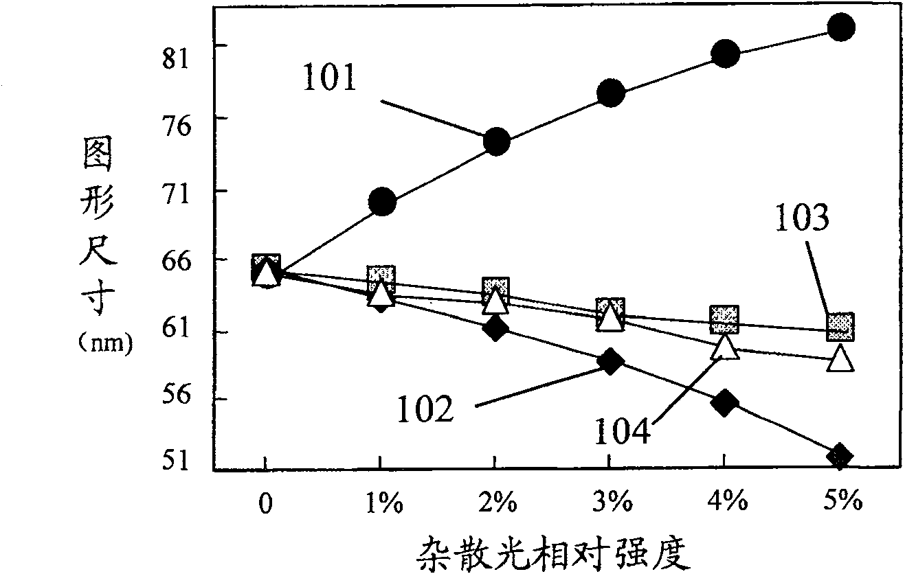
[0009] In addition, the Chinese patent application with the publication number CN1641485A published on July 20, 2005 also proposed a method for eliminating the influence of stray light on the size of photolithographic patterns. The deviation of the pattern size caused by stray light is corrected by adjusting the pattern size on the photolithography mask or changing the developing conditions, but this method does not take into account the different distribution of stray light in different regions of the entire substrate. Therefore, the deviation of pattern size due to stray light cannot be improved within the entire substrate, and the accuracy and consistency of the formed pattern still cannot meet the requirements of the existing semiconductor manufacturing technology.

Method used


Image

  • Photolith exposure method and exposure system
  • Photolith exposure method and exposure system
  • Photolith exposure method and exposure system

Examples


Embodiment Construction

[0040] In order to make the above objects, features and advantages of the present invention more comprehensible, specific implementations of the present invention will be described in detail below in conjunction with the accompanying drawings.

[0041] The processing method of the present invention can be widely used in various fields, and can utilize many suitable materials to make, and the following is to illustrate by specific embodiment, certainly the present invention is not limited to this specific embodiment, in this field Common replacements known to those of ordinary skill undoubtedly fall within the protection scope of the present invention.

[0042] Secondly, the present invention is described in detail using schematic diagrams. When describing the embodiments of the present invention in detail, for the convenience of explanation, each schematic diagram will not be partially enlarged according to the general scale, which should not be used as a limitation of the pres...


PUM


Abstract

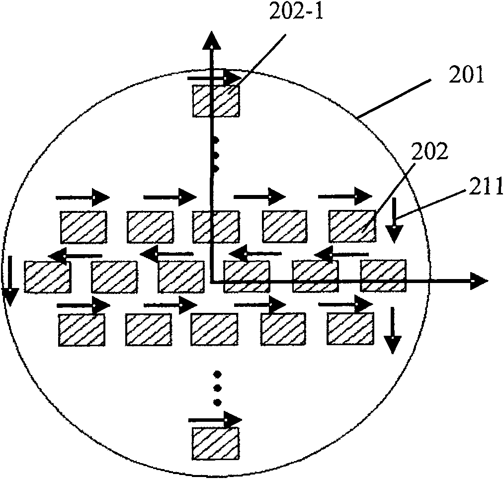
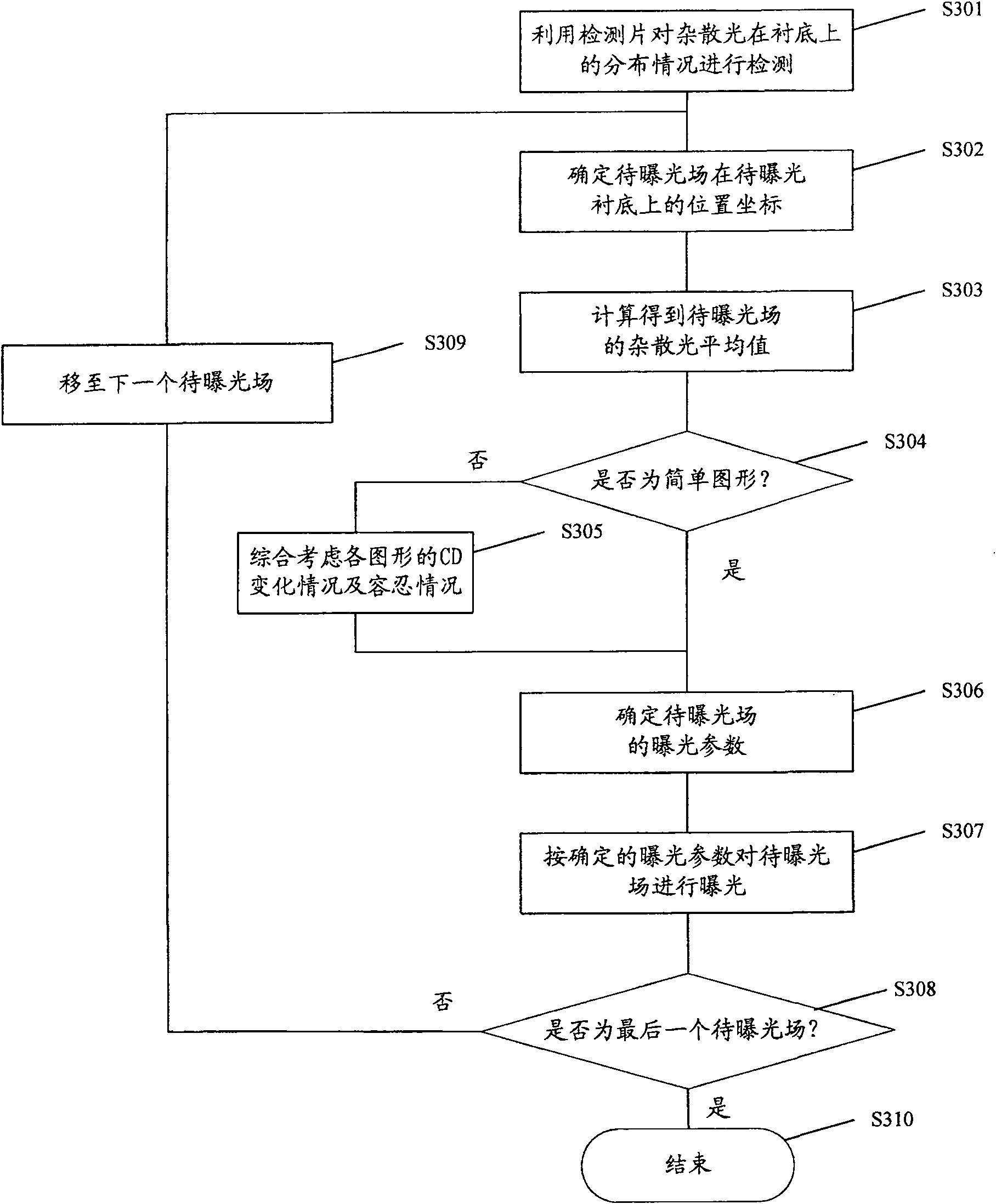
The invention discloses an exposure method of lithography, comprising the following steps: detecting the distribution of the stray light on a substrate through a detection chip; determining the location of an exposure field on the substrate; according to the stray light distribution detected by the detection chip and the determined location, calculating the average of the stray light in the exposure field; determining the exposure parameters of the exposure field, according to the average of the stray light in the exposure field; exposing the exposure field based on the exposure parameters; moving to the next field to be exposed on the substrate; and repeating the steps of determining the location of the field to be exposed, calculating the stray light average, determining the exposure parameters and exposing, until all the exposure fields on the substrate are exposed. The invention also discloses an exposure system which can realize the exposure method. The application of the exposuremethod or the exposure system can make up the stray light impact on the sizes of the formed graphics, and improve the accuracy and consistency of the sizes of the graphics.

Description

technical field [0001] The invention relates to the technical field of semiconductor manufacturing, in particular to a photolithographic exposure method and an exposure system. Background technique [0002] The production of semiconductor chips is divided into multiple layers, and the production of each layer needs to be patterned to form specific structures, such as forming contact hole structures or metal wiring structures. The pattern definition of these specific structures is usually done by photolithography. process achieved. The so-called photolithography is a process of transferring the designed structure pattern to the wafer by using a photolithography mask. In the semiconductor manufacturing process, the photolithography process is at the center and is the most important process step in the production of integrated circuits. How to accurately reflect the designed graphics on the photolithography mask and then transfer them to the semiconductor wafer is a key issue ...

Claims


Application Information

Patent Timeline
Patent Type & Authority Patents(China)
IPC IPC(8): G03F7/20H01L21/027
Inventor 张飞
Owner SEMICON MFG INT (SHANGHAI) CORP
Learn More