
voltage reference circuit

A voltage reference and circuit technology, applied in the direction of adjusting electrical variables, control/regulating systems, instruments, etc., can solve problems such as poor accuracy of voltage reference circuits

Active Publication Date: 2011-12-28
SHANGHAI HUAHONG GRACE SEMICON MFG CORP
View PDF7 Cites 0 Cited by
  • Summary
  • Abstract
  • Description
  • Claims
  • Application Information

AI Technical Summary

Problems solved by technology

[0006] Therefore, the problem in the above-mentioned prior art is that it is difficult for the two symmetrically arranged MOS transistors in the bias voltage generation circuit to have exactly the same parameters, which makes the accuracy of the voltage reference circuit poor.

Method used


Image

  • voltage reference circuit
  • voltage reference circuit
  • voltage reference circuit

Examples


Embodiment Construction

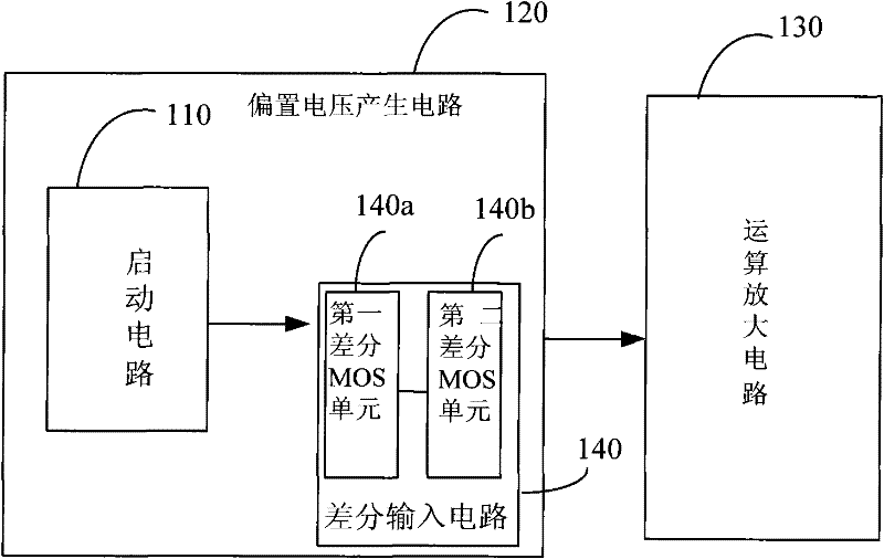
[0014] According to the background technology, it can be known that the existing voltage reference circuit usually includes a bias voltage generating circuit and an operational amplifier circuit, wherein the bias voltage generating circuit is to provide a voltage output for the operational amplifier circuit, and the bias voltage generating circuit includes a differential input circuit, which includes Two symmetrically set MOS tubes with exactly the same parameters. As is well known to those skilled in the art, since the parameters of the two MOS transistors in the differential input circuit are exactly the same, the equivalent input drift voltage of the two MOS transistors caused by temperature changes, power fluctuations, etc. is equivalent to a pair of common-mode signals, Therefore, the effects of the above changes can be canceled out.

[0015] However, due to the limitation of process conditions, it is difficult for the two MOS transistors to have the same parameters, whic...


PUM


Abstract

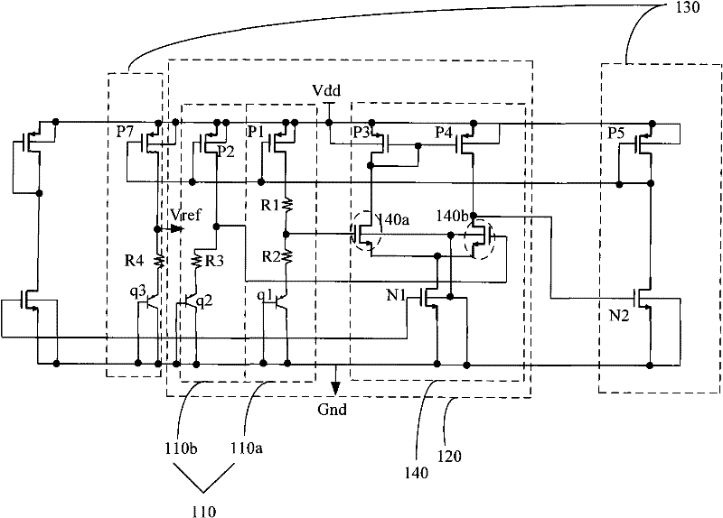
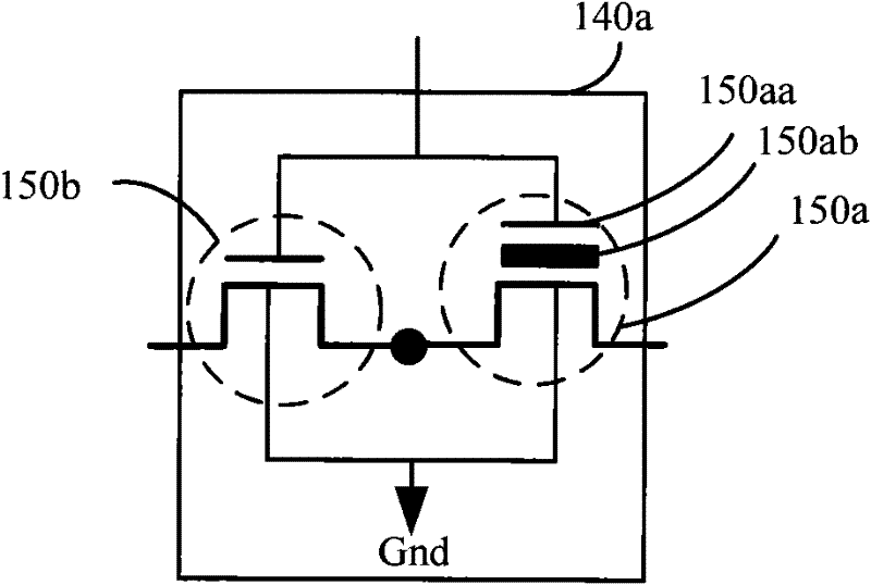
The invention provides a voltage reference circuit comprising a bias voltage generation circuit and an operational amplifying circuit, wherein the bias voltage generation circuit is used for providing the bias voltage to the operational amplifying circuit; the operational amplifying circuit is used for outputting the reference voltage; the bias voltage generation circuit comprises a differential input circuit which comprises a first differential metal oxide semiconductor (MOS) unit and a second differential MOS unit which are symmetrically arranged; the grid electrodes of the first differential MOS unit and the second differential MOS unit are respectively connected with the input end of the differential input circuit; the source electrodes of the first differential MOS unit and the second differential MOS unit are connected; the drain electrode(s) of the first differential MOS unit and / or the second differential MOS unit is / are connected with the output end of the bias voltage generation circuit; and the first differential MOS unit and the second differential MOS unit are of a broken grid storage unit structure. The voltage reference circuit provided by the invention can be used for improving the accuracy of the voltage reference circuit.

Description

technical field [0001] The invention relates to the technical field of semiconductor manufacturing, in particular to a voltage reference circuit. Background technique [0002] A voltage reference circuit (Voltage Reference) generally refers to a high-stability voltage source used as a voltage reference in a circuit. With the increasing scale of integrated circuits. Especially with the development of system integration technology (SOC), it has also become an indispensable basic circuit module in large-scale, VLSI and almost all digital and analog systems. [0003] Precise and stable voltage references are required in many integrated circuits and circuit units, such as digital-to-analog converters (DACs), analog-to-digital converters (ADCs), linear regulators, and switching regulators. In a digital-to-analog converter, the DAC selects and generates an analog output from a DC reference voltage based on the digital input signal presented at its input; in an analog-to-digital c...

Claims


Application Information

Patent Timeline
Patent Type & Authority Applications(China)
IPC IPC(8): G05F3/24
Inventor 许丹
Owner SHANGHAI HUAHONG GRACE SEMICON MFG CORP
Learn More