Crossing spiral recess heat-exchanging pipe
A technology of spiral grooves and heat exchange tubes, which is applied in heat exchange equipment, tubular elements, lighting and heating equipment, etc., can solve the problem that the heat exchange effect cannot meet the requirements, achieve a large cooling effect, and improve the effect of emission performance indicators
- Summary
- Abstract
- Description
- Claims
- Application Information
AI Technical Summary
Problems solved by technology
Method used
Image

Examples
Embodiment 1
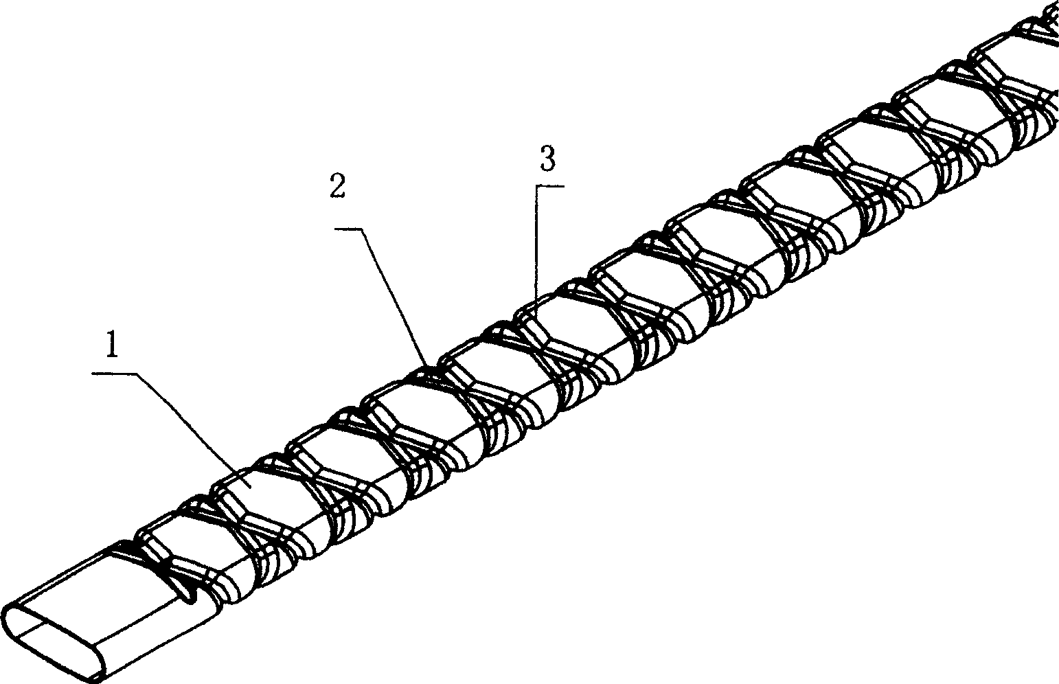
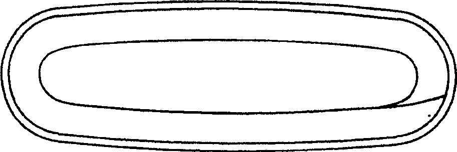
[0024] figure 1 It is a schematic diagram of the three-dimensional structure of the first embodiment of the present invention, figure 2 It is a schematic cross-sectional shape diagram of the first embodiment of the present invention. Such as figure 2 As shown, in order to make full use of the surface of the heat exchange tube to achieve heat exchange with maximum efficiency, and to facilitate production and processing, in this embodiment, when the spiral groove is removed from the heat exchange tube body, the opposite long sides and opposite sides in the section of the heat exchange tube The short sides are all arranged in an arc shape, and the long sides are smoothly connected with the short sides. The outer surface of the tube body 1 of the heat exchange tube has inwardly recessed intersecting spiral grooves 2 and 3, while the inner surface of the tube body 1 has indented intersecting spiral recesses corresponding to the grooves on the outer surface. The two ends of 1 a...
Embodiment 2
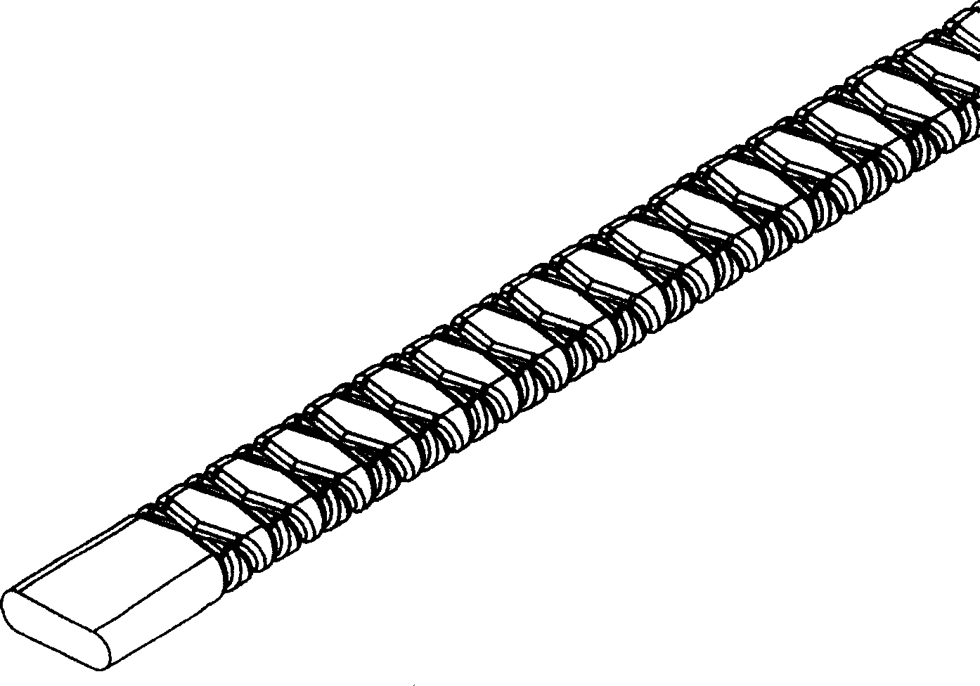
[0027] image 3 , 4 Shown are the three-dimensional structure schematic diagram and the cross-sectional shape schematic diagram of the second embodiment of the present invention respectively. The difference between this embodiment and the above-mentioned first embodiment is that the cross-sectional shape of the stainless steel pipe body is flat, the two opposite long sides are straight lines, and the opposite short sides are arc-shaped recessed semicircular arc surfaces from the inside to the outside, such as Figure 4 Shown; Other parts are identical with embodiment one. Such a setting can improve heat exchange efficiency.
[0028] Compared with the round tube, the flat tube is not centrosymmetric. The distance between the geometric center of the flat spiral tube and the tube wall is smaller than the distance between the circular spiral tube and the tube wall. Most of the fluid in the tube can participate in heat exchange. Moreover, the shape of the flat tube enhances the ...
Embodiment 3
[0030] Figure 5 , 6 Shown are the three-dimensional structure schematic diagram and the cross-sectional shape schematic diagram of the third embodiment of the present invention respectively. This embodiment is a modification on the basis of the first embodiment. The entire cross-section of the heat exchange tube is smoothly connected, that is, for the convenience of processing, the cross-sectional shape of the spiral groove is removed, and the The cross-sectional shape is set to an ellipse; other parts are the same as the first embodiment.
[0031] The non-central symmetry of the flat spiral tube is different from that of the circular spiral tube. Different arrangements can produce different effects. Therefore, according to different needs, there are many ways to arrange the heat exchange tubes. The tubes are arranged in parallel, staggered, or both in parallel and staggered. Different arrangements make the flow of the coolant outside the tubes disturbed differently, which ...
PUM
 Abstract
Description
Claims
Application Information
 - Generate Ideas
- Intellectual Property
- Life Sciences
- Materials
- Tech Scout
- Unparalleled Data Quality
- Higher Quality Content
- 60% Fewer Hallucinations
Browse by: Latest US Patents, China's latest patents, Technical Efficacy Thesaurus, Application Domain, Technology Topic, Popular Technical Reports.
© 2025 PatSnap. All rights reserved.Legal|Privacy policy|Modern Slavery Act Transparency Statement|Sitemap|About US| Contact US: help@patsnap.com