Air purifier and its control method

An air purification device and air purification technology, applied in irradiation, deodorization, disinfection, etc., can solve the problems of consumables, photocatalyst falling off, and dirty, etc., and achieve the effect of long life and easy cleaning

Inactive Publication Date: 2007-08-29
欧阳杰 +1
View PDF4 Cites 0 Cited by
  • Summary
  • Abstract
  • Description
  • Claims
  • Application Information

AI Technical Summary

Problems solved by technology

[0004] 1. When the device is working, the airflow first passes through the dust collection device and then passes through the photocatalytic reaction device. Therefore, the airflow is already charged when it reaches the photocatalytic reaction device, and the charged airflow is easy to absorb dust, so that the photocatalyst part will soon be used. It is very dirty and needs to be cleaned frequently, which will easily cause the photocatalyst to fall off and become invalid
[0005] 2. Since the photocatalytic reaction device 8' has a honeycomb structure, when the ultraviolet light source 13' is irradiated, as shown by the dotted arrow symbol in Figure 2, the surrounding light can only irradiate the inner wall of one side of the honeycomb hole, but cannot On one side of the backlight, there is a dead angle of irradiation; while the middle light passes through the honeycomb hole of the photocatalytic reaction device 8', which not only cannot make full use of the light energy, but also easily damages the eyes of the user due to the ultraviolet light emitted, so it must be re- Only by setting the plate photocatalyst part 41' can the above disadvantages be avoided, but this will make the structure complicated and increase the cost
[0006] 3. The plate-shaped photocatalyst part 41' and the plate-shaped electrostatic filter screen 40' form a roll-type filter 6'. The filter 6' cannot be cleaned, but the used filter screen is cut off after a long time, and then pulled out A new filter, so consumables will be generated, increasing the cost of use
[0007] 4. The negative ions generated by the dust collection device cannot reach the air outlet. If you want to generate negative ions in the air, you need to install a negative ion generator at the air outlet, so the cost will increase virtually.
[0008] 5. The control mode is single. Generally, the photocatalyst and the dust collection device work at the same time, and it is impossible to select different working modes according to the smoke and dust content in the air, so the operation is not flexible

Method used


Image

  • Air purifier and its control method
  • Air purifier and its control method
  • Air purifier and its control method

Examples


Embodiment Construction

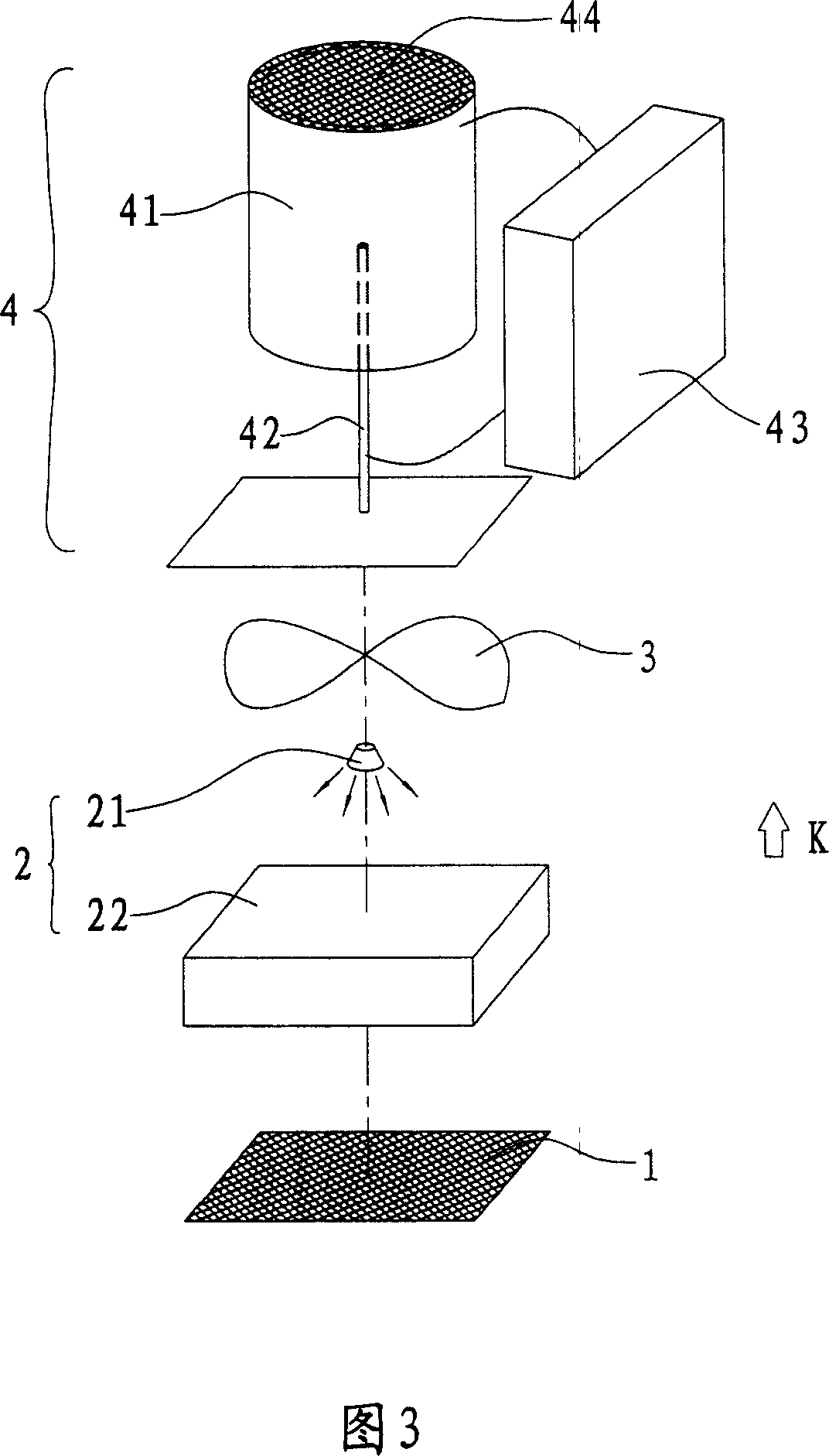
[0048] As shown in Figure 3, the present invention is in the airflow channel, along the direction of airflow K, coarse filter screen 1, photocatalyst reducing device 2, fan 3 and negative ion dust collecting device 4 are arranged successively, wherein:

[0049] Coarse filter screen 1 can filter out larger particle, dust and hair.

[0050] The photocatalyst reduction device 2 includes an ultraviolet light source 21 and a photocatalyst net 22, the ultraviolet light source 21 is an ultraviolet LED lamp, and the photocatalyst net 22 is a material coated or containing a photocatalyst, if it is sponge, it can also increase the filtering effect.

[0051] The fan 3 has the effect of circulating the air, and it can also be used to fix the ultraviolet LED lamp and the discharge tip 32 described below; and the position of the fan 3 in the airflow channel is not limited.

[0052]Negative ion dust collector 4 comprises a hollow cylindrical positive pole body 41, a discharge tip 42 and a hi...


PUM


Abstract

The air purifier includes reducing photocatalyst unit and dust collecting negative ion unit set successively in the air flow direction inside the air flow channel. When the air purifier is operated, air flow passes through first the reducing photocatalyst unit and then the dust collecting negative ion unit, and this makes no ionized air flow with attached dust adsorbed onto the photocatalyst net, no need of regular cleaning of the photocatalyst net, less material consumption and low cost. The control method makes the present invention possesses several work modes.

Description

technical field [0001] The invention relates to an air purification device, that is, an air purification device used in refrigerators, freezers, air conditioners, etc. or directly placed in rooms and automobiles and a control method thereof. Background technique [0002] With the improvement of people's living standards, people's requirements for indoor environment and air are getting higher and higher. The improvement of living standards has made refrigerators, air conditioners and other electrical appliances a must-have for ordinary families. However, refrigerators used for a long time will produce peculiar smell, and airtight air-conditioned rooms are also prone to produce peculiar smell and breed bacteria, thereby polluting indoor air and reducing people's quality of life. Therefore just have a large amount of air cleaning devices to arise at the historic moment on the market. [0003] In the prior art, air purification devices mostly use ion dust collection devices an...

Claims


Application Information

Patent Timeline
Patent Type & Authority Patents(China)
IPC IPC(8): A61L9/20A61L9/22
Inventor 欧阳伟欧阳杰
Owner 欧阳杰
Why Eureka
Try Eureka