
Perpendicular magnetic recording medium

a magnetic recording medium and perpendicular magnetic technology, applied in the field can solve the problems of insufficient orderly creation of alloys, inability to maintain stably magnetic field, insufficient magnetic anisotropy constant and coercivity of perpendicular magnetic recording medium, etc., to achieve high coercivity, reduce magnetic reversal field, and high magnetic anisotropy constant

Active Publication Date: 2018-04-10
FUJI ELECTRIC CO LTD
View PDF23 Cites 3 Cited by
  • Summary
  • Abstract
  • Description
  • Claims
  • Application Information

AI Technical Summary

Benefits of technology

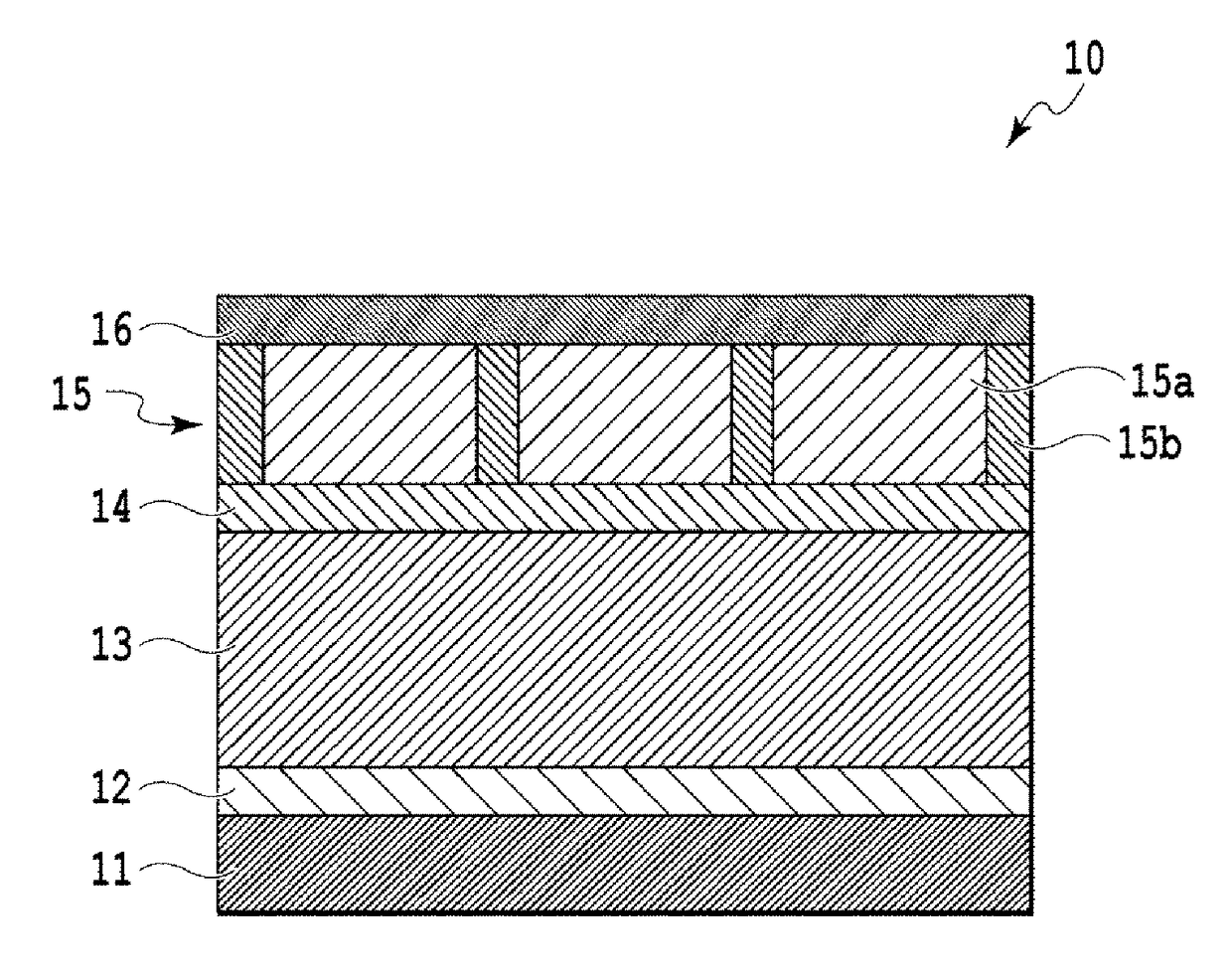
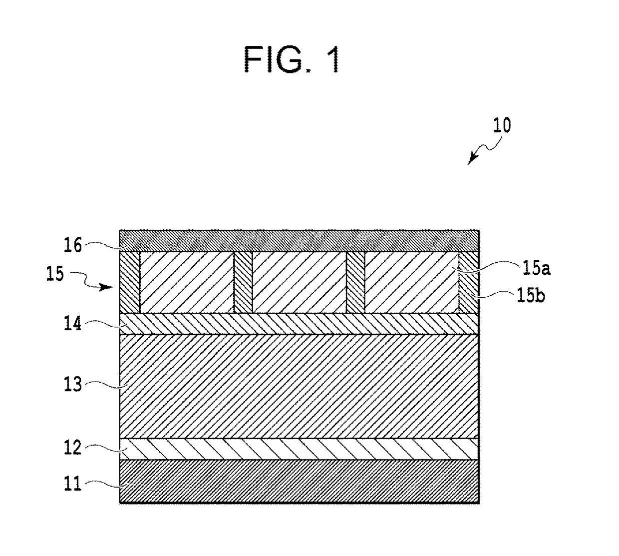
[0022]According to the present invention, it is possible to provide a perpendicular magnetic recording medium in which magnetic crystal grains are micronized to be sufficiently ordered and separated. According to the present invention, it is possible to provide a perpendicular magnetic recording medium having a high magnetic anisotropy constant Ku. According to the present invention, it is possible to provide a perpendicular magnetic recording medium having high coercivity Hc.
[0023]Further, in the present invention, when a magnetic recording layer having magnetic crystal grains containing Mn in particular and a non-magnetic crystal grain boundary containing Ge oxides is employed, it is possible to decrease a magnetic reversal field by decreasing the Curie temperature and to facilitate heat-assisted recording.
[0024]Moreover, when a granular layer containing a grain boundary material mainly composed of C (carbon) is formed, a granular layer containing oxides mainly composed of Ge is formed thereon, and different materials are added to the magnetic crystal grains of these layers, it is possible to decrease a heat-assisted recording temperature and to reduce a magnetic reversal field. Moreover, it is possible to increase a magnetic reversal field gradient.

Problems solved by technology

As a result, the size of state-of-the-art magnetic crystal grains approaches the physical limit called a superparamagnetic limit in which magnetization cannot be maintained stably due to the influence of ambient heat.
When a magnetic recording layer having a granular structure is formed using a conventional non-magnetic non-metallic material, the magnetic anisotropy constant and coercivity of the perpendicular magnetic recording medium are not satisfactory.
However, these materials could not sufficiently create an ordered structure of the alloy and separate grains, and the magnetic anisotropy and coercivity thereof were decreased.
Moreover, a perpendicular magnetic recording layer in which an FePt-based ordered alloy is granularized has various problems.

Method used


Image

  • Perpendicular magnetic recording medium
  • Perpendicular magnetic recording medium
  • Perpendicular magnetic recording medium

Examples


example 1

[0072]A chemically reinforced glass substrate (N-10 glass substrate manufactured by HOYA Corporation) was used as the non-magnetic substrate. The layers ranging from the Ta-based adhesion layer to the C-based protective film were formed using an in-line type film forming apparatus without exposing the layers to the atmosphere. A Ta-based adhesion layer having a thickness of 5 nm was formed in an Ar gas atmosphere according to a DC magnetron sputtering method using a pure Ta target. Further, a Cr-based underlayer having a thickness of 20 nm was formed in an Ar gas atmosphere according to a DC magnetron sputtering method using a pure Cr target. Subsequently, a MgO-based seed layer having a thickness of 5 nm was formed according to an RF sputtering method using a MgO target in a state where the substrate was heated to 300° C. When the MgO layer was formed, the pressure of the Ar gas atmosphere was 0.02 Pa and the RF power was 200 W. Subsequently, a FePt—GeO2 layer was formed as a magne...

example 2

[0073]A FePt—C layer was formed as the first magnetic recording layer in the following manner. Specifically, the substrate was heated to 450° C., and then, the FePt—C layer having a thickness of 2 nm was formed according to a DC magnetron sputtering method using a target including FePt and C. The target including FePt and C was adjusted so as to have a composition of 60 vol % of FePt and 40 vol % of C during deposition. When the FePt—C layer was formed, the pressure of the Ar gas atmosphere was 1.0 Pa and the input DC power was 25 W. Subsequently, a FePt—GeO2 layer was formed as the second magnetic recording layer in the following manner. Specifically, the substrate was heated to 450° C., and then, a FePt—GeO2 layer having a thickness of 7 nm was formed according to a DC magnetron sputtering method using a target including FePt and GeO2. The target including FePt and GeO2 was adjusted so as to have a composition of 75 vol % of FePt and 25 vol % of GeO2 during deposition. When the Fe...

example 3

[0074]Layers were formed using the same method as used in Example 2 except that the FePt—GeO2 layer of Example 2 had a thickness of 3 nm.


PUM

PropertyMeasurementUnit
thicknessaaaaaaaaaa
thicknessaaaaaaaaaa
thicknessaaaaaaaaaa

Abstract

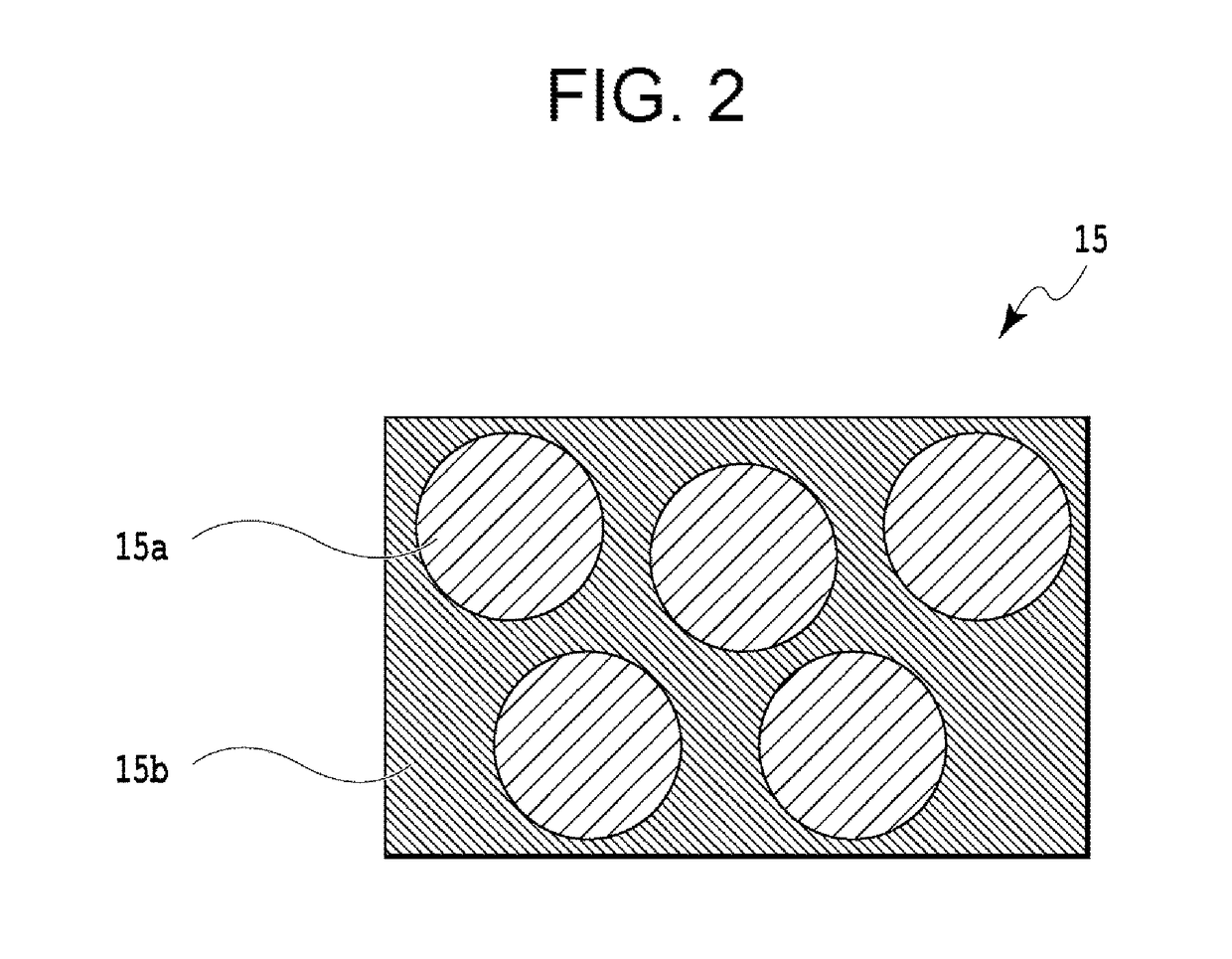
A perpendicular magnetic recording medium includes a non-magnetic substrate; and a magnetic recording layer that includes magnetic crystal grains and a non-magnetic crystal grain boundary that surrounds the magnetic crystal grains, wherein the magnetic crystal grains contain an ordered alloy and the non-magnetic crystal grain boundary contains Ge oxides. The magnetic recording layer may have a granular structure. The magnetic crystal grains may be micronized to be sufficiently ordered and separated, and the perpendicular magnetic recording medium may have a high magnetic anisotropy constant Ku and high coercivity Hc.

Description

CROSS-REFERENCE TO RELATED APPLICATION(S)[0001]This non-provisional application is a continuation of and claims the benefit of the priority of Applicant's earlier filed International Application No. PCT / JP2013 / 007199 filed Dec. 6, 2013, the entire contents of which are incorporated herein by reference.BACKGROUND OF THE INVENTION[0002]1. Field of the Invention[0003]The present invention relates to a perpendicular magnetic recording medium and, more particularly, to a perpendicular magnetic recording medium that contains Ge oxides.[0004]2. Background of the Related Art[0005]Conventionally, a perpendicular magnetic recording scheme for realizing perpendicular magnetization of a surface of a magnetic recording layer (magnetization film) of a magnetic recording medium has been used as a recording scheme of magnetic recording apparatuses. A magnetic recording medium used in the perpendicular magnetic recording (hereinafter perpendicular magnetic recording medium) includes a non-magnetic s...

Claims


Application Information

Patent Timeline
Patent Type & Authority Patents(United States)
IPC IPC(8): G11B5/66G11B5/65
CPCG11B5/66G11B5/65G11B5/672
Inventor ONO, TAKUYASHIMATSU, TAKEHITO
Owner FUJI ELECTRIC CO LTD
Learn More