Axially elongate dental machining portion

a technology of machining portion and machining portion, which is applied in the direction of tool workpiece connection, manufacturing tools, dental surgery, etc., can solve the problems of inaccuracy of laboratory implant machining, inability to accurately machining and the adhesive joint between the blank and the holder can loosen under a heavy load, so as to simplify the fixation or holding of the machining portion to the holder

Active Publication Date: 2018-04-10
STEGER HEINRICH
View PDF18 Cites 2 Cited by
  • Summary
  • Abstract
  • Description
  • Claims
  • Application Information

AI Technical Summary

Benefits of technology

[0013]Therefore, the object of the present invention is to provide a machining portion which is improved over the state of the art, and an improved holder. In particular, the invention seeks

Problems solved by technology

Another disadvantage is that the adhesive joint between the blank and the holder can come loose under a heavy loading when machining the blank.
In addition, this three-part structure (blank, holder and adapter) is rather complicated and expensive.
A disadvantage with that holding arrangement for a laboratory implant is that an elastic clamping collet is arranged between the laboratory implant and the clamping nut or the clamping chuck, whereby deformation phenomena can occur, which lead to an inaccuracy when machining the laboratory implant.
In addition, that design configuration is quite complicated and expensive as at least three different components are required to hold the laboratory implant.
The shelf portion does not serve to fix or hold the abutment and because of its low level of stability it is also not in any way suitable for that purpose but it serves only as a contact surface or abutment portion for a supraconstruction which is to be fitted later.
Thus, the machining operation automatically entails a disadvantageous loading on the delicate connection (base portion) due to the vibration occurring in the machining process.
In addition, in the machining operation detrimental high lever forces can take effect because of the relatively large spacing between the base portion and the machinable chimney portion
The manufacture of those separate components is relatively complicated and expensive.
The disadvantage here is that the abutment is only held or clamped in place laterally (in frictionally locking relationship) and there is no (positively locking) fixing in the direction of the longitudinal axis.
A disadvantage there is that the fixing region is relatively narrow

Method used


Image

  • Axially elongate dental machining portion
  • Axially elongate dental machining portion
  • Axially elongate dental machining portion

Examples


first embodiment

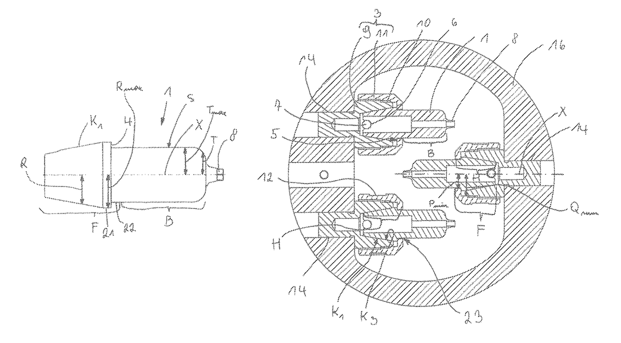
[0054]FIG. 11 shows an alternative embodiment of a holder 3, wherein, in particular, the base element 9 is of an alternative configuration in the region remote from the machining portion 1. In principle, the base element 9 itself again has a male thread as part of the cap nut 11 and the conical region K3. It is also possible to see the fitting pin 7. The cap nut 11 and the machining portion 1 are practically identical to the As a substantial difference, the limit switch 20 can also be fixed to the base element 9, as can be seen, in particular, from FIG. 12. That limit switch 20 corresponds to an abutment disposed on the machine. Conversely, the abutment instead of the limit switch 20 can also be arranged on the base element 9. The section A-A shown in FIG. 12a is also clearly illustrated in FIG. 12b, wherein, besides the fixing projection 9 and the holding nose 5, it is also possible to see in this sectional view the fitting pin 7 which engages into the positioning groove 6. The li...

second embodiment

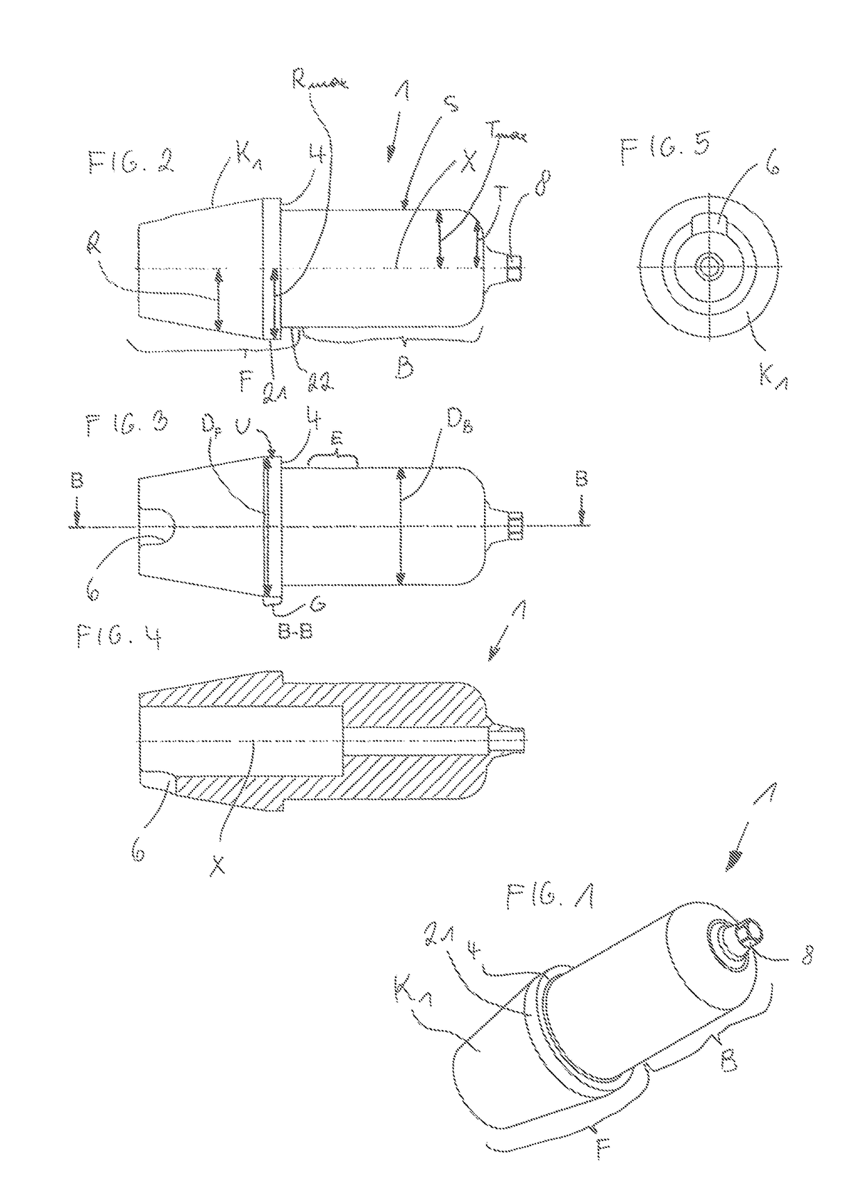
[0058]FIGS. 23 and 24 show a machining portion 1. With this or also another kind of external geometry, it is possible to carry out a scan prior to the machining operation (that is to say, prior to the cutting process) with that machining portion 1. Hitherto, separate scan markers have been used to determine the position and inclination of the implants disposed in the jaw of the patient. A machining portion 1 involving the external geometry as shown in FIGS. 23 and 24 can be used in non-machined form, as such a scan marker. Then, in a second step, the desired part is milled in the machining device 2.

[0059]FIG. 25 shows a dental machining portion 1 in the form of a dental construction which is as yet unmachined. In that respect, in substance, the same advantages and variants apply in terms of fixing and manufacture, as for the abutment. In particular, the fixing region F is of the same dimensions. The machining region B can possibly be of a larger diameter than in the case of the abut...


PUM

PropertyMeasurementUnit
Fractionaaaaaaaaaa
Fractionaaaaaaaaaa
Fractionaaaaaaaaaa

Abstract

An axially elongate dental machining portion includes a machining region machinable by a dental machining device, and a fixing region for fixing the axially elongate dental machining portion to a holder of the dental machining device. In the fixing region is a fixing projection oriented transversely relative to a longitudinal axis. In a condition of the machining portion being mounted in the holder, the fixing projection bears against a holding nose positioned in complementary relationship on the holder. The machining region has a machinable surface which has a maximum spacing relative to the longitudinal axis, measured normal to the longitudinal axis, and the fixing projection has a maximum spacing relative to the longitudinal axis, measured normal relative to the longitudinal axis, that is greater than the maximum spacing of the machinable surface relative to the longitudinal axis.

Description

BACKGROUND OF THE INVENTION1. Field of the Invention[0001]The invention concerns an axially elongate dental machining portion, in particular an abutment or dental construction like a crown or bridge, comprising a machining region machinable by a dental machining device, and a fixing region for fixing the machining portion to a holder of the machining device. The invention also concerns an axially elongate holder for holding a dental machining portion, having a holding region for the dental machining portion. In addition, the invention concerns a set having at least one such machining portion and such a holder. The invention further concerns a dental machining device.2. Description of the Related Art[0002]There are numerous possible ways in the dental industry of producing various parts which form a dental prosthesis. A variant in that respect is the manual production of various parts. Increasingly, however, in recent times, entire machining devices are also used, with which dental p...

Claims


Application Information

Patent Timeline
IPC IPC(8): B23C5/00B23C3/00A61C5/77A61C8/00A61C13/00B23B31/02B23B31/20B23C1/04B24B19/26B23Q3/06
CPCA61C13/0022A61C8/005A61C13/0004B23B31/201B23C3/00B23Q3/062A61C5/77Y10T409/309016B23B2231/20B23B2231/2005B23C1/04B23C2240/12B23C2270/08B23Q3/061B24B19/26Y10T29/5107Y10T29/5176Y10T279/17504Y10T279/17871Y10T279/17881Y10T409/307168A61C8/0051A61C13/081A61C1/084B23C1/00
Inventor STEGER, HEINRICH
Owner STEGER HEINRICH
Why Eureka
Try Eureka