Concrete reinforcement assembly, method of installation, and method to determine cyclic load response
a technology of concrete reinforcement and cyclic load, applied in the direction of structural elements, building components, material strength using steady shearing force, etc., can solve the problems of cyclic motion of the anchor-infill assembly, expanding cracks in the surrounding concrete structure, and little attention in the past focusing on the problem of energy transfer and dampening energy transfer
- Summary
- Abstract
- Description
- Claims
- Application Information
AI Technical Summary
Benefits of technology
Problems solved by technology
Method used
Image
Examples
example 1
Loading History
[0100]FIG. 11 shows an exemplary loading history employed for plotting the cyclic response of a concrete reinforcement assembly along with a snapshot of a load-displacement response. The loading history has been divided in three parts. The first part represents a condition without indentation (NI) where the concrete at a bottom of the hollow cavity is strong enough that it does not become crushed under an applied load, hence resulting in no negative displacement as seen on FIG. 11. The second part is the one with no resistance (NR) where the anchor bar never comes in contact with the bottom of the hollow cavity, and hence, no resistance is offered against negative displacements. The third part is with indentation (WI) where the bottom of the hollow cavity crushes slightly to allow for negative displacements.
[0101]FIG. 12A, FIG. 12B, FIG. 12C, and FIG. 12D shows a diagram of cyclic response of the concrete reinforcement assembly described herein along with the step-by-...
example 2
Cyclic Shear-Lag Material Model
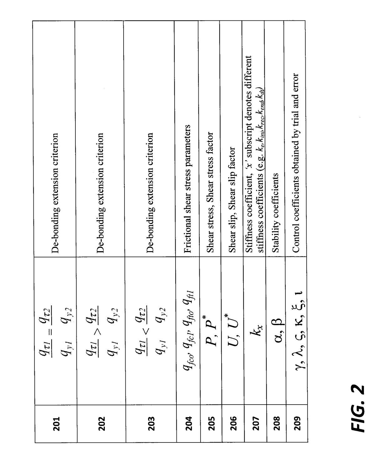
[0104]FIG. 5 represents a piecewise linear cyclic pull-out push-in shear-lag material model representing the local bond behavior of the post-installed anchor bar along with the step-by-step conceptual local response of the anchor-infill assembly presented at each stage. The vertical axis represents the shear stress, qτ, and the horizontal axis represents the shear slip, U. The positive part of the cycle represents pull-out while the negative part represents push-in. The material model is divided into two categories, namely with indentation and without indentation. The cyclic response of each category is further broken into six paths starting with S1, the elastic loading cyclic, during which the stiffness is taken as ke representing the initial elastic stiffness of the interface before any de-bonding. After reaching the tensile yield strength, gyrI, there is a sudden drop in the force accompanied with the de-bonding at the interface (S2) and reduction i...
example 3
Cyclic Rules Applied
[0106]Rules for getting the pull-out push-in cyclic load-displacement response for with- and without-indentation cycles have been formulated based on the piecewise linear cyclic shear-lag material model shown in FIG. 13A. The experimental investigation about the local bond behavior of the deformed steel bar under cyclic loading was the guideline during the formation of the following rules. The cycle without indentation cycle is divided into six paths while the cycle with indentation is divided into nine paths, with stiffness revisal incorporated at each stage in order to represent the stiffness degradation due to de-bonding and stiffness recovery due to lateral pressure effect. First, considering the cyclic pull-out push-in load-displacement response without the indentation which is represented by the loading cycle abc′cdd′e in FIG. 13A, six points recognized for getting this loading cycle are (Pa,Ua), (Pb,Ub), (Pc′,Uc′), (Pc,Uc), (Pd,Ud) and (Pd′,Ud′). Rules for...
PUM
| Property | Measurement | Unit |
|---|---|---|
| elastic modulus | aaaaa | aaaaa |
| radius | aaaaa | aaaaa |
| mechanical | aaaaa | aaaaa |
Abstract
Description
Claims
Application Information
 - R&D
- Intellectual Property
- Life Sciences
- Materials
- Tech Scout
- Unparalleled Data Quality
- Higher Quality Content
- 60% Fewer Hallucinations
Browse by: Latest US Patents, China's latest patents, Technical Efficacy Thesaurus, Application Domain, Technology Topic, Popular Technical Reports.
© 2025 PatSnap. All rights reserved.Legal|Privacy policy|Modern Slavery Act Transparency Statement|Sitemap|About US| Contact US: help@patsnap.com


