Lithography apparatus with segmented mirror

a lithography apparatus and mirror technology, applied in the field of lithography apparatus, can solve the problems of insufficient transparency of materials in the wavelength range mentioned, the inability to produce mirrors such as such a large diameter, and the inability to meet the requirements of such sizes,

Active Publication Date: 2017-12-19
CARL ZEISS SMT GMBH
View PDF24 Cites 1 Cited by
  • Summary
  • Abstract
  • Description
  • Claims
  • Application Information

AI Technical Summary

Benefits of technology

[0009]Arranging the sensor in the interspace between the mirror segments enables the relative positions of the mirror segments to be detected and regulated in a particularly space-saving manner. Consequently, it is no longer necessary to provide a plurality of sensors for each of the mirror segments outside the mirror. In order to detect the absolute position of the individual mirror segments, it suffices if the absolute position of a reference mirror segment is known, e.g. because the latter is detected by external sensors or because the latter is fixed relative to a reference point. The position of the other mirror segments can then be detected with the aid of sensors arranged between the mirror segments. Such a referencing makes it possible to detect so-called common-mode errors, that is to say positional errors that are common to all the mirror segments.
[0016]The sensor can also be a pressure sensor which generates a sensor signal dependent on the pressure in the interspace, wherein the interspace is configured in such a way that a relative movement of the mirror segments brings about a pressure change in the interspace. With such a pressure sensor, it is possible to achieve a good linearity of the sensor signal relative to changes in the position of the mirror segments.

Problems solved by technology

Furthermore, there is no material which is sufficiently transparent in the wavelength range mentioned, for which reason mirrors are used as optical elements for shaping and guiding the EUV radiation.
However, mirrors having such a large diameter are costly to produce.
Furthermore, the availability of blanks or semi-finished parts for such sizes is encountering its limits.
Moreover, with large mirror diameters, low-deformation mounting and actuation is also made more difficult.
One difficulty which arises in this case, however, is that of precisely joining together the finished polished mirror segments.
Since the different mirror segments together are intended to produce a single optical surface, the surface deviation, that is to say the difference in height between the mirror segments, should not be more than 20 nm, but this proves to be difficult.
This means that, for example in the case of four mirror segments, a total of 24 sensors have to be provided, which entails a considerable outlay and space requirement.

Method used


Image

  • Lithography apparatus with segmented mirror
  • Lithography apparatus with segmented mirror
  • Lithography apparatus with segmented mirror

Examples


Embodiment Construction

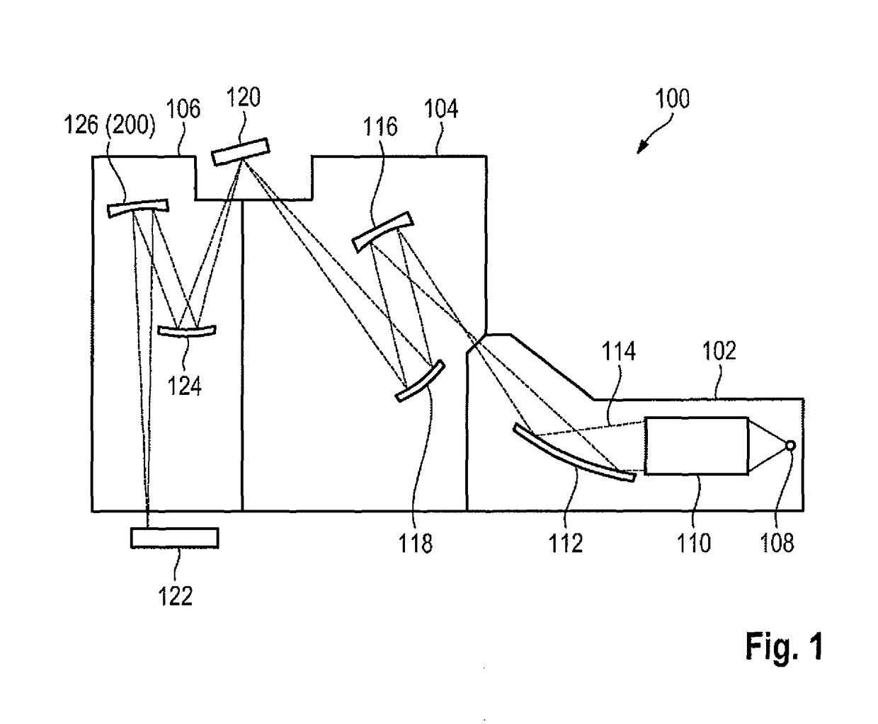
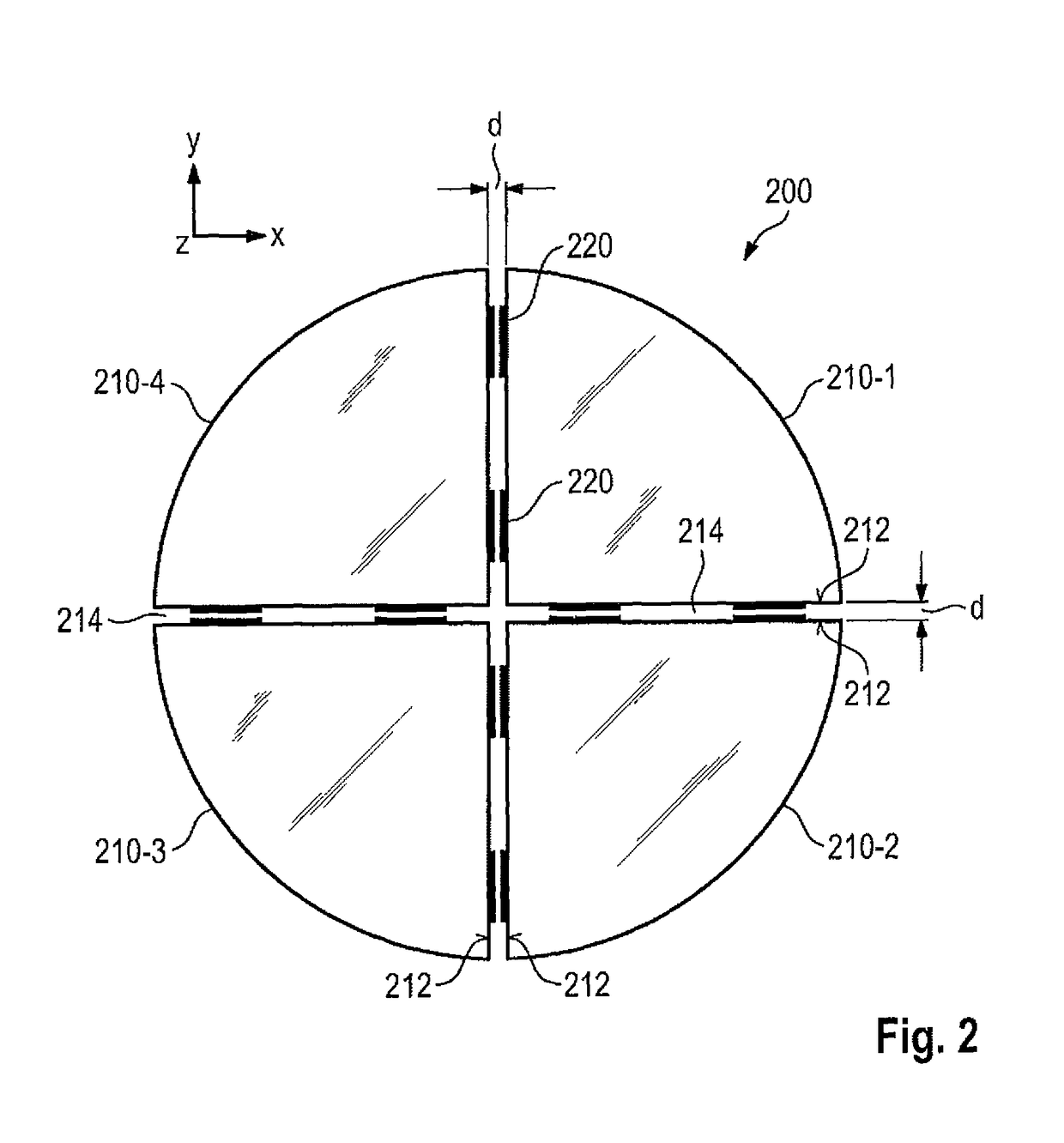
[0035]FIG. 1 shows a schematic view of an EUV lithography apparatus 100 in accordance with one embodiment, which comprises a beam shaping system 102, an illumination system 104 and a projection system 106. The beam shaping system 102, the illumination system 104 and the projection system 106 are in each case provided in a vacuum housing which can be evacuated with the aid of an evacuation device (not illustrated in greater detail). The vacuum housings are surrounded by a machine room (not illustrated in greater detail) in which e.g. the drive devices for mechanically moving and / or adjusting the optical elements are provided. Furthermore, electrical controllers and the like can also be provided in the machine room.

[0036]The beam shaping system 102 comprises an EUV light source 108, a collimator 110 and a monochromator 112. As EUV light source 108, it is possible to provide a plasma source or a synchrotron, for example, which emit radiation in the EUV range (extreme ultraviolet range)...


PUM

PropertyMeasurementUnit
optical wavelengthsaaaaaaaaaa
diametersaaaaaaaaaa
heightaaaaaaaaaa

Abstract

A lithography apparatus is disclosed, which comprises a mirror having at least two mirror segments which are joined together in such a way that an interspace is formed between the mirror segments, and a sensor for detecting the relative position of the mirror segments, wherein the sensor is arranged in the interspace between the mirror segments.

Description

CROSS-REFERENCE TO RELATED APPLICATIONS[0001]The present application is a continuation of, and claims priority under 35 USC 120 to, international application PCT / EP2013 / 062735, filed Jun. 19, 2013, which claims benefit under 35 USC 119 of German patent application DE 10 2012 212 064.5, (filed on Jul. 11, 2012. International application PCT / EP2013 / 062735 also claims priority under 35 USC 119(e) to U.S. patent application 61 / 670,215, filed on Jul. 11, 2012. The entire disclosure of each of these applications is incorporated by reference herein.FIELD OF THE INVENTION[0002]The invention relates to a lithography apparatus comprising one or more segmented mirrors.RELATED ART[0003]Lithography apparatuses are used for example in the production of integrated circuits or ICs in order to image a mask pattern in a mask onto a substrate, such as e.g. a silicon wafer. To this end, a light beam generated by an illumination device is directed through the mask onto the substrate. An exposure lens co...

Claims


Application Information

Patent Timeline
Patent Type & Authority Patents(United States)
IPC IPC(8): G03B27/54G03B27/72G03F7/20G01L21/22G01B13/12G01B7/14
CPCG03F7/7085G01L21/22G03F7/702G03F7/70233G03F7/70591G01B7/14G01B13/12
Inventor HARTJES, JOACHIM
Owner CARL ZEISS SMT GMBH
Why Eureka
Try Eureka