Torsional vibration reducing device
a torsional vibration and reducing device technology, applied in the direction of spring/damper, rotational vibration suppression, vibration suppression adjustment, etc., can solve the problem of possible deterioration of damping performance, reduce sliding friction, and improve damping performance.
- Summary
- Abstract
- Description
- Claims
- Application Information
AI Technical Summary
Benefits of technology
Problems solved by technology
Method used
Image
Examples
first embodiment
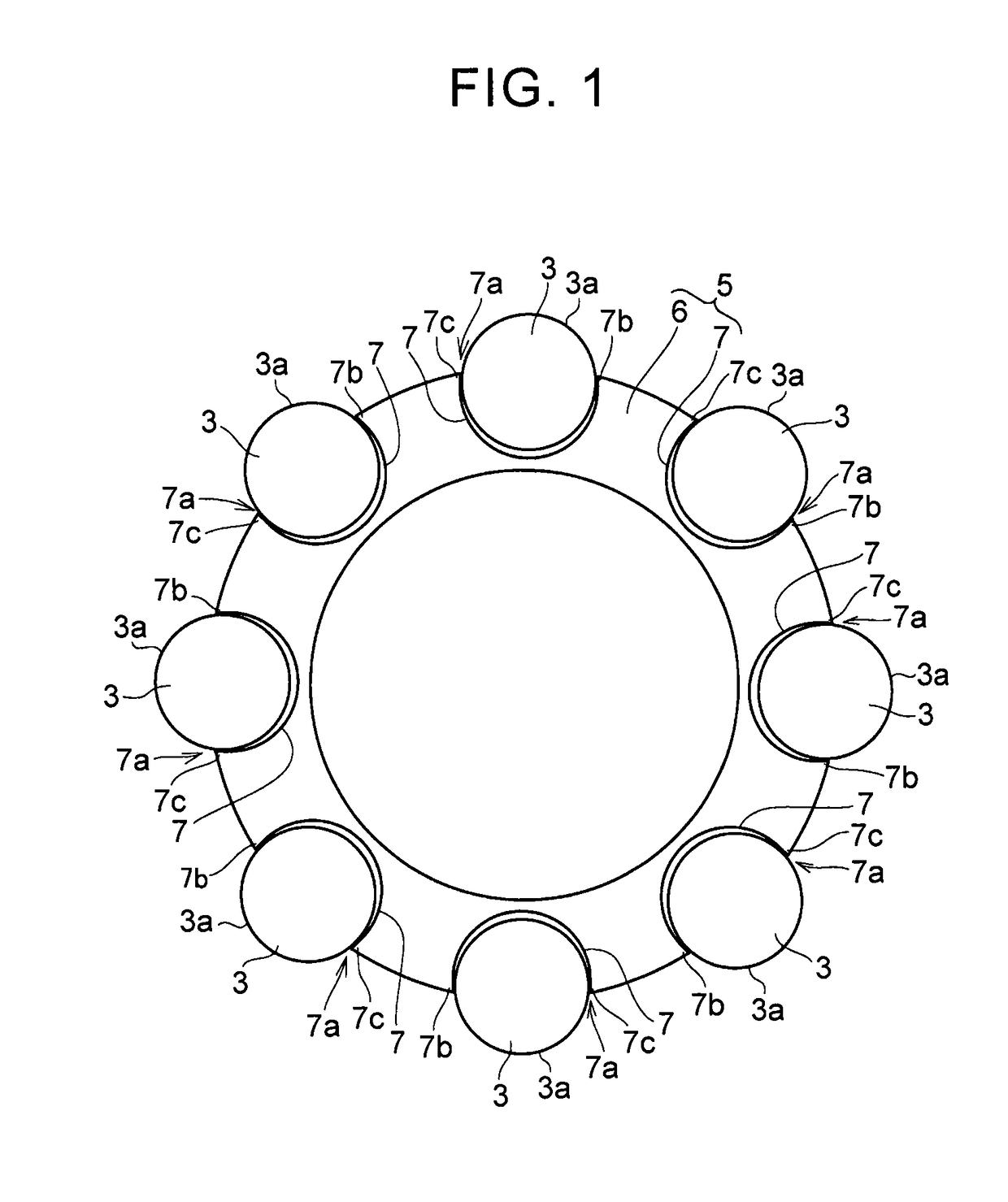
[0027]FIG. 3 is a sectional view illustrating a portion in one example of a torsional vibration reducing device according to a first embodiment. The torsional vibration reducing device includes a rotating body 1 that is attached to an object to be damped. The rotating body 1 is a disk-shaped member. Circumferentially-long guide holes 2 are formed at positions radially shifted from the center of rotation of the rotating body 1. The guide holes 2 are formed passing through the rotating body 1 in a plate thickness direction. The guide holes 2 are positioned at predetermined intervals in a circumferential direction of the rotating body 1. As one example, eight guide holes are provided. The guide holes 2 have a shape formed by curving an oval shape or an elliptical shape.
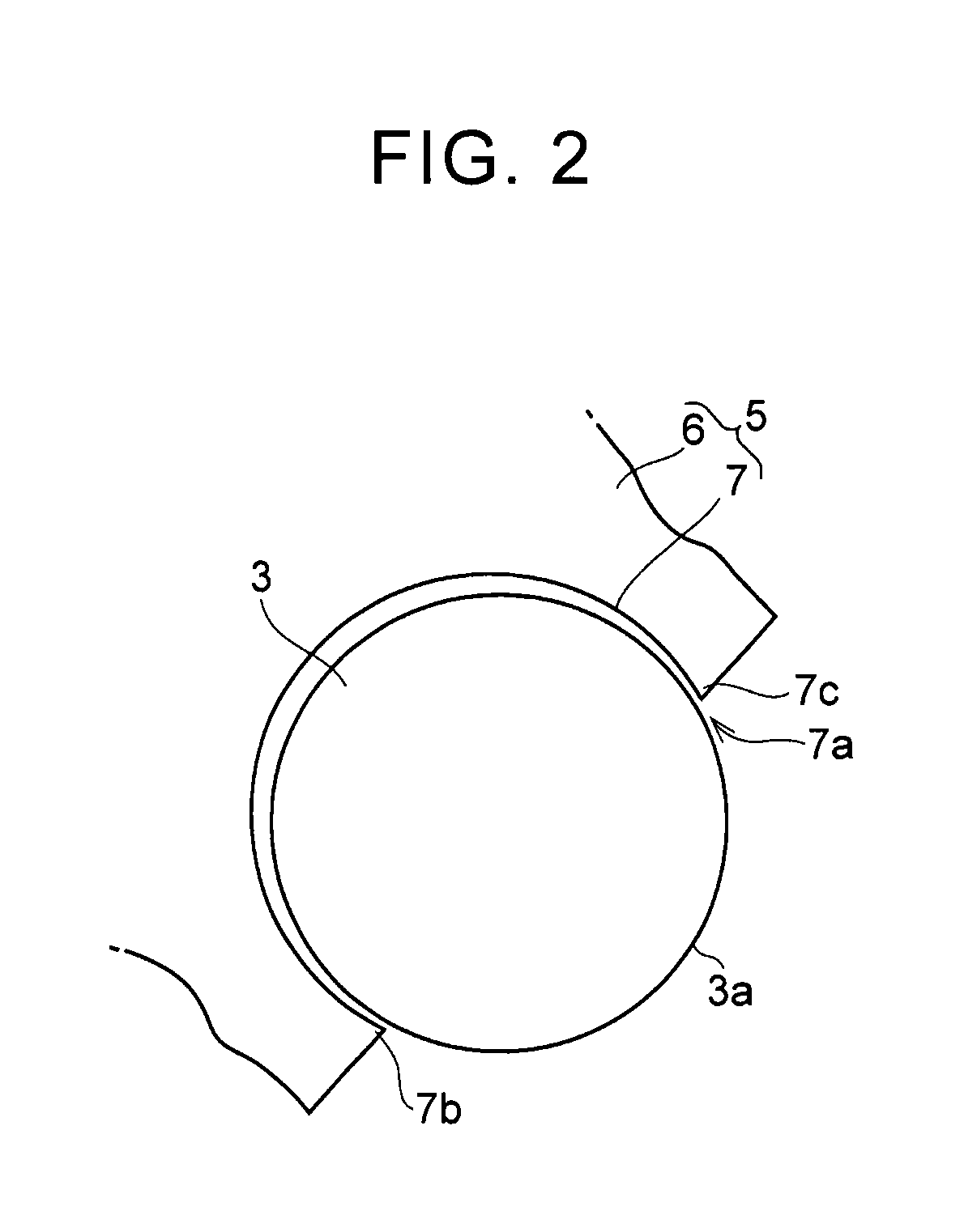
[0028]A rolling body 3 that reciprocates by an inertial force when torque transmitted to the rotating body 1 fluctuates is inserted into each of the guide holes 2. The rolling body 3 is pressed against an inner surface o...
second embodiment
[0037]FIG. 4 is a sectional view in the rotating body radial direction illustrating a portion in one example of a torsional vibration reducing device according to a second embodiment. The example shown therein is an example in which the connection members 5 are disposed on the inner side of the rolling body 3 in the radial direction of the rotating body 1 and on the opposite end portion sides of the rolling body 3 in the axial direction. In a configuration shown in FIG. 4, a load associated with contact between the outer peripheral surface 3a of the rolling body 3 and the connection members 5 is applied to the opposite end portions of the rolling body 3 in the axial direction. Therefore, the rolling body 3 can be more stably reciprocated than the example shown in FIG. 3, so that the damping performance is further improved.
third embodiment
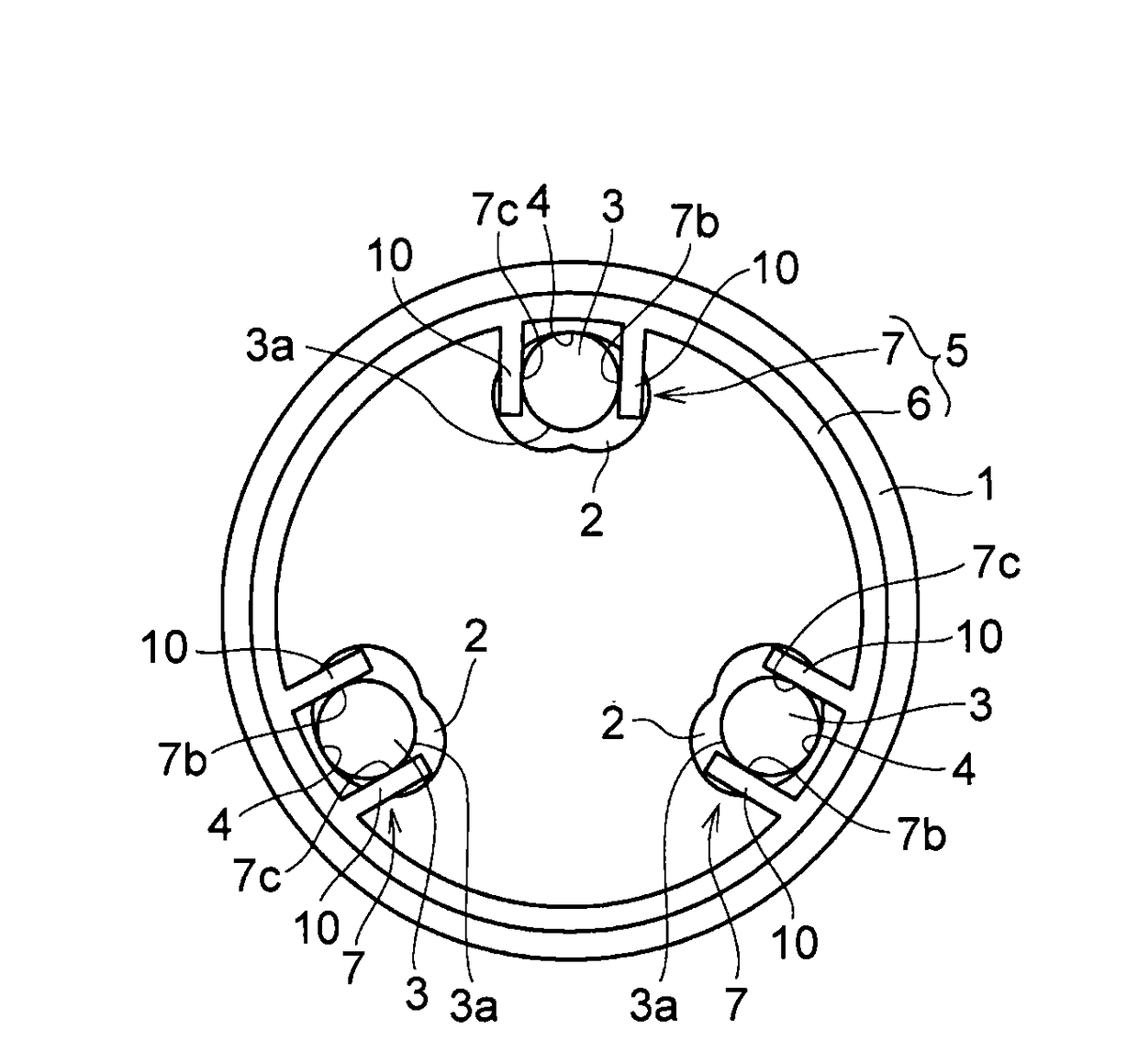
[0038]FIG. 5 is a view illustrating one example of a connection member according to a third embodiment. In the example shown in FIG. 5, the three guide holes 2 are formed at predetermined intervals in the circumferential direction of the rotating body 1. The support portion 6 in the connection member 5 has a Y shape. The support portion 6 is formed such that free end portions are positioned corresponding to the guide holes 2, respectively. The accommodating portions 7 having the opening portions 7a that open outward in the radial direction of the rotating body1 are provided at the free end portions, respectively.
PUM
 Abstract
Description
Claims
Application Information
 - R&D
- Intellectual Property
- Life Sciences
- Materials
- Tech Scout
- Unparalleled Data Quality
- Higher Quality Content
- 60% Fewer Hallucinations
Browse by: Latest US Patents, China's latest patents, Technical Efficacy Thesaurus, Application Domain, Technology Topic, Popular Technical Reports.
© 2025 PatSnap. All rights reserved.Legal|Privacy policy|Modern Slavery Act Transparency Statement|Sitemap|About US| Contact US: help@patsnap.com


