Conjugate roller drive

Inactive Publication Date: 2010-08-26
SMITH THOMAS DAVID
View PDF17 Cites 14 Cited by
  • Summary
  • Abstract
  • Description
  • Claims
  • Application Information

AI Technical Summary

Benefits of technology

[0002]This invention provides improvements to worm drives for mechanical power transmission and roller wheels and the worm screws for use in such drives. The principal innovation is utilizing conjugate mesh between the worm screw and the roller wheel by shaping both the driving surfaces of the threads of the worm screw and the driven surfaces of the roller tips so that they become conjugate surfaces that accomplish the most efficient energy transfer. This provides improved power transfer efficiency with respect to that accomplished using conventional worm drives.
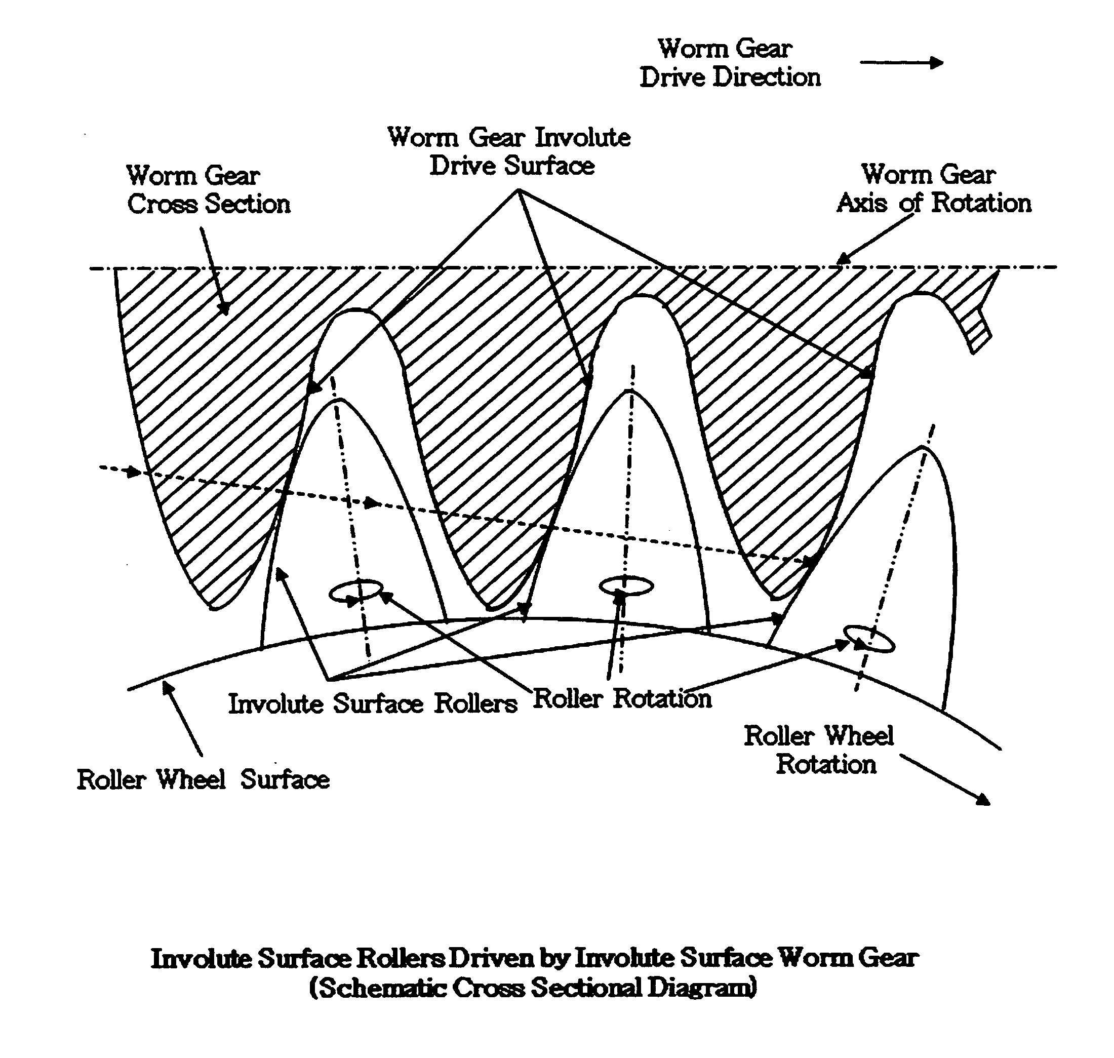
[0005]As disclosed in U.S. Pat. No. 626,515, issued Jun. 6, 1899, these frictional losses can be reduced substantially if the wheel is provided with rollers in contact with worm gear threads rather than fixed teeth. As taught by the 626,515 patent, the rollers may be arranged so that the axis of each roller extends substantially in a radial direction with respect to the axis of the roller wheel, and each roller may be mounted to the roller wheel by means of anti-friction bearings. Each roller has a tip projecting outwardly from the body of the wheel. As the worm screw rotates, the worm screw thread surfaces engage the tips of successive rollers and drive the wheel in rotation. Each roller is free to rotate about its own axis relative to the roller wheel, substantially decreasing sliding friction between the roller tips and the worm screw thread surfaces.
[0007]The principal contribution of U.S. Pat. No. 4,833,934 was the spring loading of the rollers by mounting them in thrust bearings to allow limited axial outward / inward translation of roller tips along each individual roller axis during the drive cycle in order to increase the contact time between the worm screw threads and the tips of the rollers during the drive cycle. In practice, the axial motion by spring action was effective at relatively slow rotational speeds. At high speeds, however, said axial motion became incomplete because the cycle time of each roller became shortened such that there was insufficient time for the spring action to force the roller to recover in an outward direction to the optimum outboard position before contact with the worm gear drive surface at the beginning of the next cycle. The present invention eliminates the need for spring loaded rollers by maintaining optimum contact throughout the entire drive cycle regardless of the rotational speed of the roller wheel.

Problems solved by technology

This has caused greater energy losses in the gearing mechanism with corresponding decreased power transfer efficiency.
With this mechanism, there is sliding motion between the surfaces of the worm gear threads and the surfaces of the teeth on the gear wheel hence considerable friction resulting in considerable heat generation and corresponding mechanical power loss.
At high speeds, however, said axial motion became incomplete because the cycle time of each roller became shortened such that there was insufficient time for the spring action to force the roller to recover in an outward direction to the optimum outboard position before contact with the worm gear drive surface at the beginning of the next cycle.

Method used


Image

  • Conjugate roller drive
  • Conjugate roller drive
  • Conjugate roller drive

Examples


Embodiment Construction

[0028]A worm drive according to one embodiment of the present invention, depicted in FIG. 5 includes a roller wheel 10 and a worm screw 12. The roller wheel 10 includes a body 16 defining a body axis 18. The body is mounted for rotation about body axis 18 by appropriate bearings (not shown) or equivalent means. A plurality of bores 20, are formed in body 16, the bores being disposed in a common plane and extending substantially radially with respect to body axis 18, the bores being spaced at equal intervals about the periphery of the body 16.

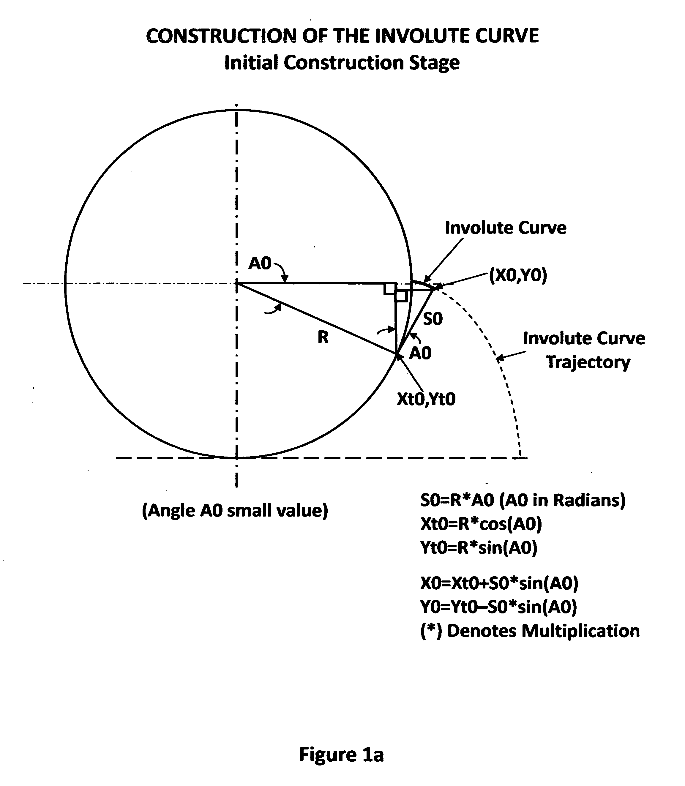
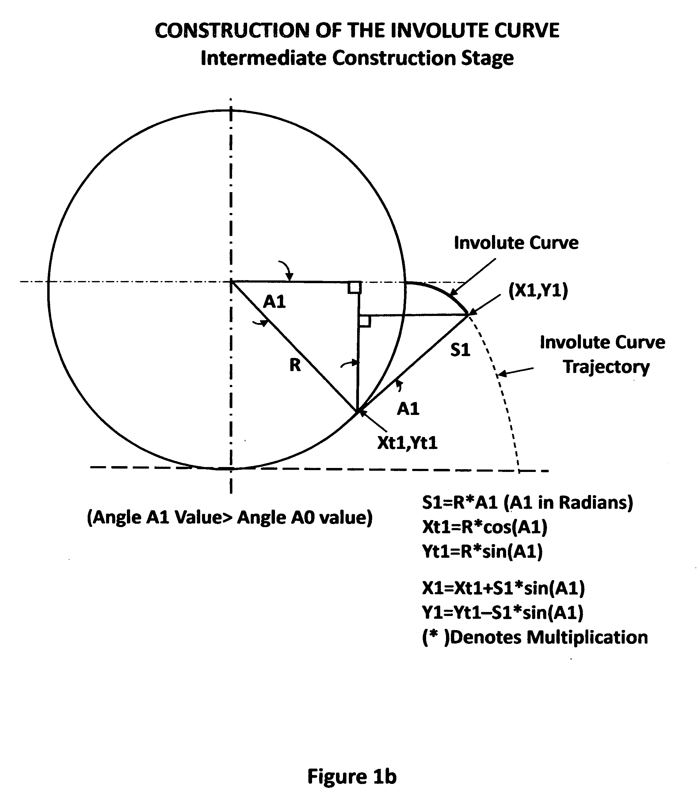
[0029]A plurality of rollers 22 are carried on body 16. Each roller tip 26 is in the form of a figure of revolution of an involute curve about a roller axis 24. The rollers 22 are received in bores 20 so that the roller axes 24 extend radially with respect to body axis 18. Directions and locations along each roller axis 24 are specified herein as either “inboard” or “outboard”. As used herein, the term “inboard” means the direction along the rol...


PUM


Abstract

This invention provides improvements to worm drives for mechanical power transmission and roller wheels and the worm screws for use in such drives. The principal innovation is utilizing conjugate mesh between the worm screw and the roller wheel by shaping both the surfaces of the threads of the worm screw and the driven surfaces of the roller tips so that they become conjugate surfaces that accomplish the most efficient energy transfer.Previous worm drive approaches have emphasized conforming shapes for the roller tips and the worm screw as well as certain other techniques in an attempt to compensate certain inherent limitations to energy transfer between driving and driven surfaces. This has caused greater energy losses in the gearing mechanism with corresponding decreased power transfer efficiency. The use of conjugate shapes for the roller tips and the driving worm gear surface represents a significant improvement to the concept.

Description

BACKGROUND OF THE INVENTION[0001]This application claims priority to U.S. Provisional Patent Application No. 61 / 208,160 entitled CONJUGATE ROLLER DRIVE filed Feb. 23, 2009 which is incorporated herein by reference for all purposes.[0002]This invention provides improvements to worm drives for mechanical power transmission and roller wheels and the worm screws for use in such drives. The principal innovation is utilizing conjugate mesh between the worm screw and the roller wheel by shaping both the driving surfaces of the threads of the worm screw and the driven surfaces of the roller tips so that they become conjugate surfaces that accomplish the most efficient energy transfer. This provides improved power transfer efficiency with respect to that accomplished using conventional worm drives.[0003]Previous worm drive approaches have emphasized conforming shapes for the roller tips and the worm screw as well as certain other techniques in an attempt to compensate certain inherent limita...

Claims


Application Information

Patent Timeline
IPC IPC(8): F16H1/16F16H55/17F16H55/22
CPCF16H1/166Y10T74/19981Y10T74/19828F16H55/22
Inventor SMITH, THOMAS DAVID
Owner SMITH THOMAS DAVID
Why Eureka
Try Eureka