
Cold-formed tank head for railroad tank car

a tank car and cold-formed technology, applied in the field of cold-formed tank car head for railroad tank car, can solve the problems of multiple tank car fire and explosion near the town center, high equipment cost and time consumption, and achieve the effect of easy adaptability

Inactive Publication Date: 2017-09-26
SAMUEL SON
View PDF21 Cites 5 Cited by
  • Summary
  • Abstract
  • Description
  • Claims
  • Application Information

AI Technical Summary

Benefits of technology

The method reduces production costs and time, minimizes material damage, and enhances the adaptability of tank head manufacturing, while meeting or exceeding safety standards for impact toughness, thus improving the safety and efficiency of railroad tank car heads.

Problems solved by technology

This process is expensive in terms of equipment and is time consuming.
The AAR standards do not contemplate or address tank car heads fabricated through a cold forming process and then heat treated after cold forming.
In that incident, a freight train with seventy-two tank cars filled with crude oil ran away and derailed, resulting in the fire and explosion of multiple tank cars near the town's center.
In addition to the casualties, more than thirty buildings were destroyed.
Just outside of Casselton, a train carrying crude oil struck wreckage from a prior derailment on Dec. 30, 2013, igniting the crude oil and causing a chain of large explosions which were heard and felt several miles away.
One drawback of early cold-forming approaches is that the equipment was limited to a single tank car head size specification.
Changing the set-up of the press equipment from one tank head size to another added further time and expense.
More importantly, the use of brute force to cold-form a tank car head in a very short period of time may cause material damage and introduce significant stresses in the material.
Where the steel blank is over ⅜ of an inch thick, finite cracks are highly suspect in rapid cold-forming operations.
Thus, rapidly cold-formed tank car heads have in the past required very careful and time-consuming inspection.

Method used


Image

  • Cold-formed tank head for railroad tank car
  • Cold-formed tank head for railroad tank car
  • Cold-formed tank head for railroad tank car

Examples


Embodiment Construction

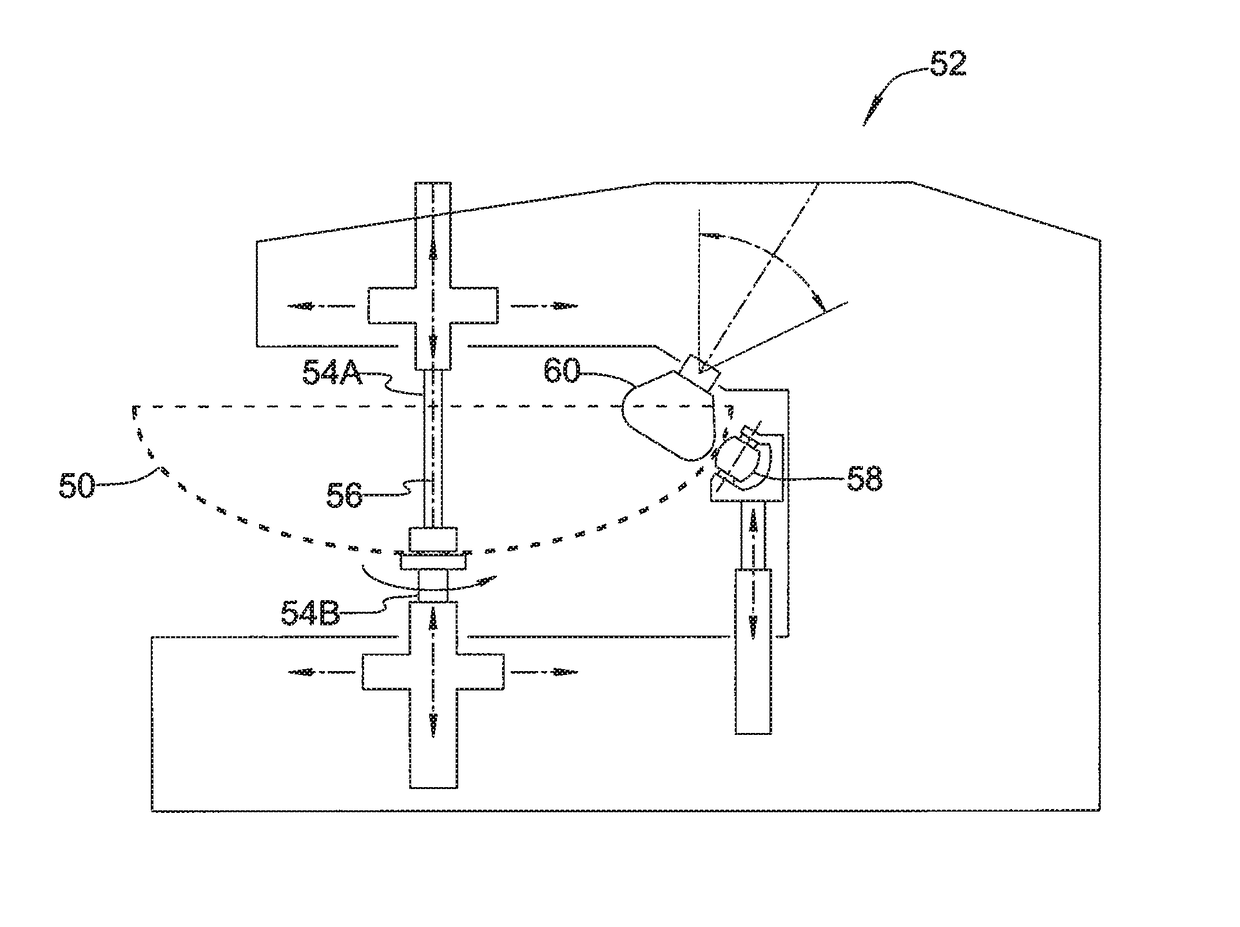
[0031]FIG. 1 generally illustrates a method 10 of manufacturing an ellipsoidal head for a railroad tank car in accordance with an embodiment of the present invention. The method described herein may be used to produce tank car heads for DOT / TC Pressure Cars (Class DOT / TC-105, 112, 114 &120 tank cars). Heads for these tank car classifications are currently produced using a hot forming and normalizing process described above in the Background of the Invention section.

[0032]As an initial step indicated at block 12, a circular blank of steel plate material is provided. The circular blank, shown in FIGS. 2 and 3 and identified by reference numeral 30, may be cut from flat plate stock material using a plasma cutter, laser cutter, or other steel cutting technology. Circular blank 30 may be cut from ASTM TC128, Grade B, normalized steel plate, a grade intended for usage in railroad tank car fabrication (this is the only grade approved in North America and Europe for usage in railroad tank c...


PUM

PropertyMeasurementUnit
temperatureaaaaaaaaaa

Abstract

A method of manufacturing a railroad car tank head includes the steps of providing a circular blank of steel plate material, cold-forming the circular blank to form an intermediate ellipsoidal dish, cold-forming a peripheral flange region of the intermediate ellipsoidal dish to form a flanged ellipsoidal dish, and heat treating the flanged ellipsoidal dish. The heat treatment may be either a thermal stress relieving heat treatment or a normalizing heat treatment. The two cold-forming steps may be carried out at room temperature. The present invention provides a method of making a railroad car tank head that is more efficient than prior methods, avoids the challenges of hot-forming and single-stage cold-forming, is easily adaptable to different tank head diameters using the same forming equipment, and yields a railroad car tank head that meets safety standards.

Description

FIELD OF THE INVENTION[0001]The present invention relates generally to railroad tank cars used to carry liquids and gases, including hazardous and flammable liquids and gases. More specifically, the present invention relates to a method of forming “2:1” ellipsoidal heads for cylindrical tanks of railroad tank cars from steel, and to railroad car tank heads made by such method. A “2:1” ellipsoidal head is shaped as an ellipsoid of revolution in which the major axis equals the diameter of the tank shell adjacent the head and the minor axis equals one-half the major axis.BACKGROUND OF THE INVENTION[0002]Material properties and specifications associated with tank heads used on rail tank cars are directed by the Association of American Railroads (“AAR”) under AAR Specification M-1002 entitled “AAR Manual of Standards and Recommended Practices, Section C-Part III, Specification for Tank Cars.” AAR Specification M-1002 is governed by DOT 173.31(f), which states:[0003](f) Special requiremen...

Claims


Application Information

Patent Timeline
Patent Type & Authority Patents(United States)
IPC IPC(8): C21D9/00C21D8/02B21D51/18B21D19/00C21D1/30B21D31/00
CPCC21D9/0068B21D31/005B21D19/00B21D51/18C21D8/0221C21D8/0247C21D1/30B21D22/185B61D5/00B61D5/08
Inventor STANCESCU, DANIEL P.BALAZ, RICHARD M.ASSAAD, EMAD FAKHRY HABIB
Owner SAMUEL SON
Learn More