Control apparatus and control method for internal combustion engine

a control apparatus and internal combustion engine technology, applied in mechanical apparatus, electric control, machines/engines, etc., can solve the problems of increasing deteriorating the properties of the exhaust gas discharged from the combustion chamber the deterioration of the drivability of the internal combustion engine, so as to reduce the fluctuation of the spray shape, the effect of reducing the fluctuation of the needle lift amount and reducing the deterioration of the exhaus

Active Publication Date: 2017-09-05
TOYOTA JIDOSHA KK
View PDF10 Cites 0 Cited by
  • Summary
  • Abstract
  • Description
  • Claims
  • Application Information

AI Technical Summary

Benefits of technology

[0008]This invention provides a fuel injection control apparatus and a control method for an internal combustion engine which suppresses deterioration of the combustion properties and drivability, in cases where divided injection control is executed.
[0022]In the control method relating to a second aspect of this invention, a division number increase control may be executed by the ECU, when the value of the spray shape parameter is smaller than the division number reduction determination value. The division number reduction control may be control to increase the number of partial lift injections in one engine cycle and to shorten an injection time of each of the partial lift injections. According to this, the number of divisions is increased when there is a possibility of the fluctuation of the spray shape coming within a tolerable range (in other words, of the spray shape parameter being kept at or below the division number reduction determination value), even if the number of divisions is increased. Therefore, it is possible to gain the advantage of divided injection more effectively.

Problems solved by technology

Therefore, in the partial lift injection, there is a possibility of greater fluctuation in the needle lift amount, compared to full lift injection.
When fluctuation in the shape of the spray occurs, the properties of the exhaust gas discharged from the combustion chamber of the internal combustion engine deteriorate, and drivability becomes worse.

Method used


Image

  • Control apparatus and control method for internal combustion engine
  • Control apparatus and control method for internal combustion engine
  • Control apparatus and control method for internal combustion engine

Examples


first embodiment

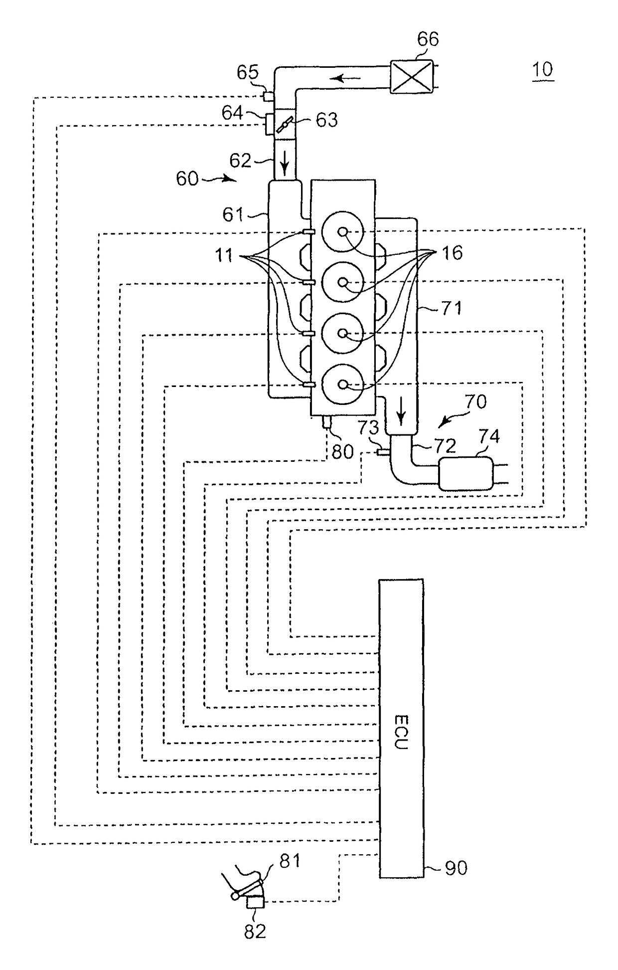
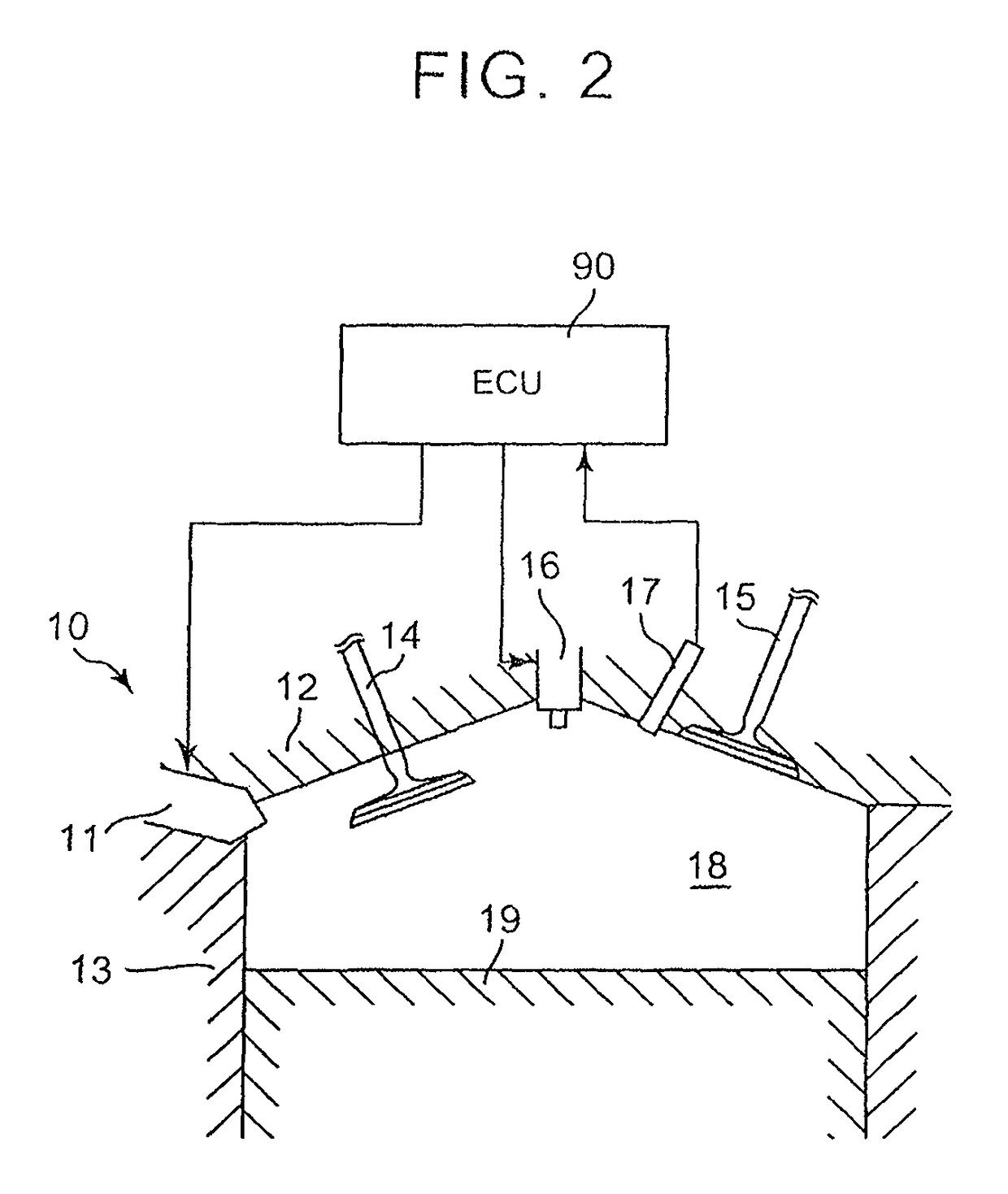
[0049]Below, this invention is described below with reference to the drawings. The internal combustion engine to which the combustion fuel control apparatus according to this invention can be applied is shown in FIGS. 1 and 2. In FIGS. 1 and 2, numeral 10 represents a main body of the internal combustion engine (“engine main body” below), numeral 11 represents a fuel injection valve, numeral 12 represents a cylinder head, numeral 13 represents a cylinder block, numeral 14 represents an intake valve, numeral 15 represents an exhaust valve, numeral 16 represents an ignition plug, numeral 17 represents a cylinder internal pressure sensor, numeral 18 represents a combustion chamber, numeral 19 represents a piston, numeral 60 represents an air intake passage, numeral 61 represents an air intake manifold, numeral 62 represents an air intake pipe, numeral 63 represents a throttle valve, numeral 64 represents a throttle valve actuator, numeral 65 represents an air flow meter, numeral 66 rep...

second embodiment

[0078]The division number control is described next. In some of the embodiments described below, the configuration and control of respective embodiments which are not described are respectively the same as the configuration and control of the other embodiments which are described in this specification, or are a configuration and control that could evidently be deduced from the configuration and control of the other embodiments upon considering the configuration or control of the respective embodiments.

[0079]In the division number control according to the second embodiment, when divided Injection is carried out, if the spray shape parameter is greater than the division number reduction determination value, then the number of divisions obtained by reducing the current target number of divisions by one is set as the new target number of divisions. In this case, since fuel of the target injection amount is injected from the fuel injection valve by a reduced number of partial lift injec...

third embodiment

[0087]The division number control is described next. In this control, if the spray shape parameter relating to any one cylinder (called “particular cylinder” below) is greater than the division number reduction determination value when divided injection is executed, then the number of divisions obtained by reducing the current target number of divisions by one is set as the new target number of divisions for the cylinder in question. In this case, since fuel of the target injection amount is injected from the fuel injection valve by a reduced number of partial lift injections in respect of the cylinder in question, then the injection time of each partial lift injection becomes longer.

[0088]If the spray shape parameter is still larger than the division number reduction determination value after having reduced the target number of divisions relating to the cylinder in question, then the execution of divided injection is prohibited in relation to that cylinder, and the number of divis...


PUM


Abstract

A control apparatus for an internal combustion engine, wherein the internal combustion engine includes a fuel injection valve injecting fuel directly into a cylinder. The control apparatus includes an ECU. The ECU is configured to execute a divided injection control to inject fuel from the fuel injection valve by a plurality of partial lift injections. The ECU is configured to execute a division number reduction control when the value of a spray shape parameter representing spray shape fluctuation is greater than a division number reduction determination value. The division number reduction control is control to reduce the number of partial lift injections in one engine cycle and to lengthen an injection time of each of the partial lift injections.

Description

CROSS-REFERENCE TO RELATED APPLICATIONS[0001]This is a national phase application based on the PCT International Patent Application No. PCT / IB2014 / 001630 filed Aug. 28, 2014, claiming priority to Japanese Patent Application No. 2013-181432 filed Sep. 2, 2013, the entire contents of both of which are incorporated herein by reference.BACKGROUND OF THE INVENTION[0002]1. Field of the Invention[0003]This invention relates to a control apparatus and a control method for an internal combustion engine.[0004]2. Description of Related Art[0005]Japanese Patent Application Publication No. 2003-21024 (JP 2003-21024 A) discloses the implementation of a plurality of partial lift injections for lifting a needle valve by a smaller amount than a full lift amount.SUMMARY OF THE INVENTION[0006]The partial lift injection is an injection which starts closing of the needle valve before the needle lift amount reaches the full lift amount. Therefore, in the partial lift injection, there is a possibility of ...

Claims


Application Information

Patent Timeline
Patent Type & Authority Patents(United States)
IPC IPC(8): F02D41/40F02M61/04F02M51/06F02D41/30
CPCF02D41/3005F02D41/402F02M51/06F02M61/04Y02T10/44Y02T10/40
Inventor MITANI, SHINICHIUCHIDA, DAISUKEKANEKO, NAOYAHOSHI, KENJIADACHI, HIROAKIHASHIMOTO, SUSUMU
Owner TOYOTA JIDOSHA KK
Why Eureka
Try Eureka