Protective goalie skate boot body with integral blade mounting channel

a technology of blade mounting and goalie skate boot, which is applied in the field of protecting goalie skate boot with integral blade mounting channel, can solve the problems of loss of movement velocity, insufficient rigid coupling of thermoformed plastic boot to the skate blade, and inability to provide movement velocity, etc., and achieves the effects of reducing width, reducing flexing and bending, and reducing angl

Active Publication Date: 2017-07-04
VH FOOTWEAR INC
View PDF15 Cites 8 Cited by
  • Summary
  • Abstract
  • Description
  • Claims
  • Application Information

AI Technical Summary

Benefits of technology

The current invention is a new goalie skate design that eliminates the need for a plastic cowling. It is made from carbon fiber, which provides better protection and flexibility compared to traditional goalie skates. The blade is held in a plastic channel that is encased in carbon fiber, and the support structure is made in one step, eliminating flexing and bending. The composite materials used in the support structure provide more protection, so an outer plastic cowling is not required. The reduced width of the skate allows for quicker pushes and the blade can be positioned optimally during fabrication. Overall, the current invention provides better performance, comfort, and flexibility for goalies.

Problems solved by technology

i) The thermoformed plastic boot does not provide an adequately rigid coupling to the skate blade through the riveted plastic cowling.
Therefore, as the goalie attempts to make quick movements from one side of their goalie crease to the other energy, and the resulting movement velocity, is lost through flexing and bending of the traditional goalie skate.
iii) Because the plastic cowling encloses the bottom half of the boot there is not the ability for the boot position, relative to the plastic cowling and blade, to be modified and optimized.

Method used


Image

  • Protective goalie skate boot body with integral blade mounting channel
  • Protective goalie skate boot body with integral blade mounting channel
  • Protective goalie skate boot body with integral blade mounting channel

Examples


Embodiment Construction

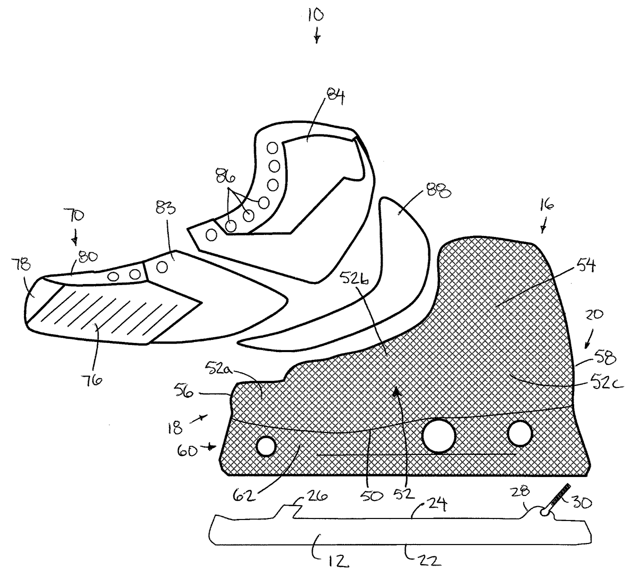
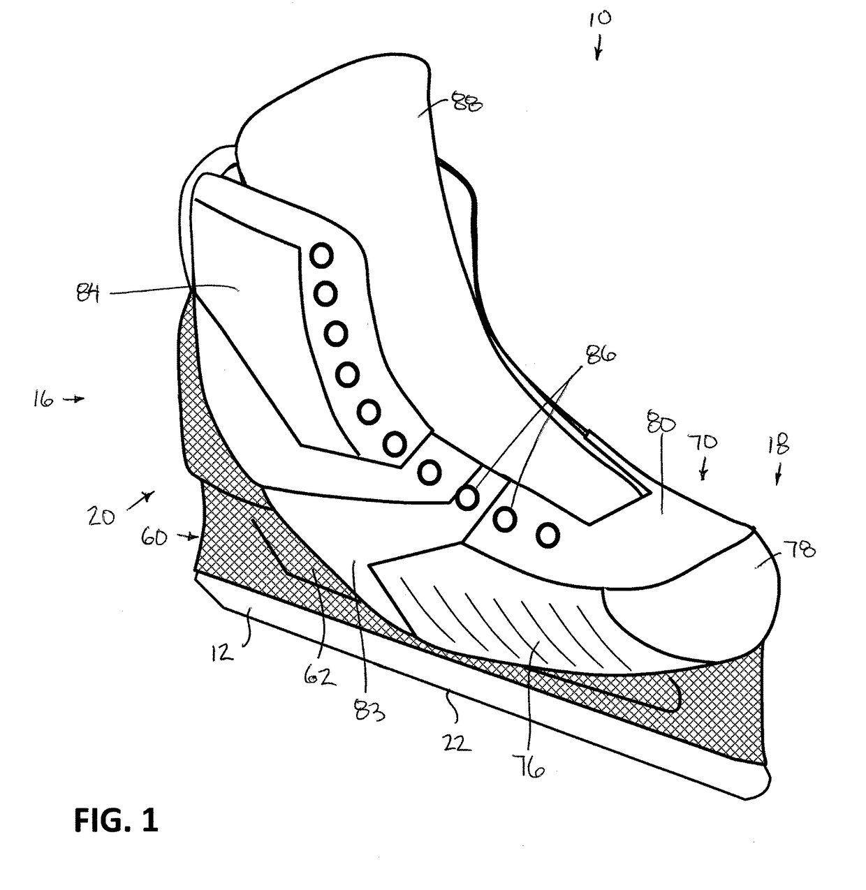
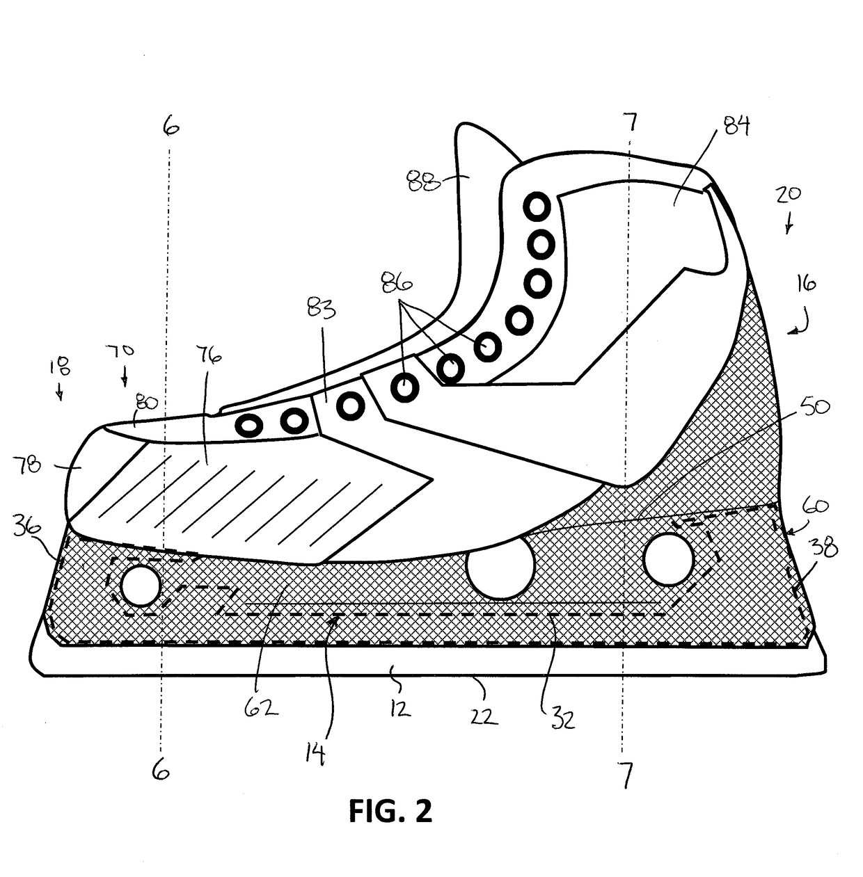
[0049]FIG. 1 shows the current invention. FIG. 2 shows a lateral view of the current invention with the location of the blade holder component shown with a dashed line, as the blade holder component is encased in a composite material within the monocoque skate body. In one embodiment of the current invention the blade holder component is a molded nylon plastic piece. FIG. 3 shows an exploded view of the current invention. When assembled the toe cap is first stitched to the quarter panel then the combined component is bonded and stitched to the monocoque skate body. As can be noted from FIG. 3 and FIG. 4 the monocoque skate body does not cover the top of the toe box section and therefore the toe cap is required to provide protection to the top of the wearer's toe. FIG. 3 and FIG. 4 also show a bolt and hook system formed on the top of the skate blade that allow the skate blade to be removably attached to the blade holder component.

[0050]FIG. 4a is a cross sectional view of the monoco...


PUM

PropertyMeasurementUnit
lengthaaaaaaaaaa
speedaaaaaaaaaa
velocityaaaaaaaaaa

Abstract

A goalie skate assembly has i) a plastic blade mounting member adapted to releasably receive a metal skate blade therein, and ii) a monocoque carbon fiber and resin composite skate boot body for receiving a foot of the user therein. The unitary structure of the skate boot body includes i) a sole portion, ii) a heel portion extending upwardly from the sole portion for receiving a heel of the user therein, iii) a pair of side portions extending upwardly from opposing sides of the sole portion, and iv) a lower portion extending downwardly from a bottom side of the sole portion so as to surround at least a portion of the blade mounting member. A toe cap mounted on the skate boot body includes a molded plastic outer shell and a liner formed of a fiber and resin composite material bonded to an inner surface of the outer shell.

Description

FIELD OF THE INVENTION[0001]The present invention relates to an ice skate used in the sport of hockey, and more particularly, the present invention relates to a skate used by a hockey goalie in which i) the skate boot body is formed to be sufficiently rigid to provide puck impact protection without requiring a separate protective shell or cowling to be mounted externally on the skate boot body, ii) the skate boot body integrally supports a blade receiving channel thereon, and / or iii) a toe cap of the skate boot is formed of molded plastic, subsequently lined with a composite fibre and resin material.BACKGROUND[0002]In ice hockey there are typically two main positions: goalie and player. The player carries the hockey puck throughout the ice surface, which requires a skate that allows for acceleration, top end speed, tight turning, and fast stopping. The goalie, on the other hand, protects their net from hockey pucks passing the goal line, and therefore does not venture far from the n...

Claims


Application Information

Patent Timeline
Patent Type & Authority Patents(United States)
IPC IPC(8): A63C1/02A43B23/26A63C1/42B29D35/02A43C5/00A43B23/08A43B1/14A43D3/02A43B5/16B29K105/06B29K307/04
CPCA43B5/1683A43D3/02A43B5/1641A43B1/14A43B23/087A43C5/00A43B23/26A63C1/42A63C1/02B29D35/02B29K2105/06B29K2307/04A43B5/16A43B5/1625A43B23/0225A43B23/0235A43B23/086A63C1/303B29D35/0054B29D35/12A63C2201/02A63C2203/20A63C2203/42
Inventor VAN HORNE, SCOTT
Owner VH FOOTWEAR INC
Why Eureka
Try Eureka