Method of manufacturing sealed body and method of manufacturing light-emitting device

a technology of sealing body and light-emitting device, which is applied in the direction of solid-state devices, electric lighting sources, electric light sources, etc., can solve the problems of reducing the yield of sealed bodies, achieve low reflectivity, reduce the amount of reflected laser light entering the frit glass, and improve the effect of sealing

Inactive Publication Date: 2017-05-30
SEMICON ENERGY LAB CO LTD
View PDF61 Cites 3 Cited by
  • Summary
  • Abstract
  • Description
  • Claims
  • Application Information

AI Technical Summary

Benefits of technology

[0010]In the above conventional method for preventing generation of a crack in the overlap region, conditions of laser light irradiation need to be controlled in a complex manner, which has been troublesome. Further, when the conditions of laser light irradiation are adjusted in a wrong manner, a crack is generated in the frit glass in the overlap region; thus, the yield of a sealed body is reduced.
[0011]In view of this, an object of the present invention is to provide methods of manufacturing a sealed body and a light-emitting device with high airtightness in which generation of a crack in a substrate and a frit glass in an overlap region where laser light irradiation is started and ended is prevented.
[0017]When heat the amount of which is large enough to weld the frit glass to the second substrate is applied to the frit glass, the frit glass and the second substrate are thermally expanded. Due to a difference in thermal expansion coefficient therebetween, a crack is generated in the frit glass. In the present invention, the low-reflectivity region having lower reflectivity with respect to laser light than the other regions is provided in the overlap region so that the amount of reflected laser light which enters the frit glass is reduced; thus, the amount of heat applied to the frit glass in the overlap region and that to the frit glass in the other regions can be substantially equal to each other. Therefore, a sealed body with high airtightness in which a crack is less likely to be generated in the frit glass in the overlap region can be provided.
[0023]When heat the amount of which is large enough to weld the frit glass to the second substrate is applied to the frit glass, the frit glass and the second substrate are thermally expanded. Due to a difference in thermal expansion coefficient therebetween, a crack is generated in the frit glass. In the present invention, the low-reflectivity region having lower reflectivity with respect to laser light than the other regions is provided in the overlap region so that the amount of reflected laser light which enters the frit glass is reduced; thus, the amount of heat applied to the frit glass in the overlap region and that to the frit glass in the other regions can be substantially equal to each other. Therefore, a light-emitting device with high airtightness in which a crack is less likely to be generated in the frit glass in the overlap region can be provided.
[0024]According to the present invention, methods of manufacturing a sealed body and a light-emitting device with high airtightness can be provided.

Problems solved by technology

In the above conventional method for preventing generation of a crack in the overlap region, conditions of laser light irradiation need to be controlled in a complex manner, which has been troublesome.
Further, when the conditions of laser light irradiation are adjusted in a wrong manner, a crack is generated in the frit glass in the overlap region; thus, the yield of a sealed body is reduced.

Method used


Image

  • Method of manufacturing sealed body and method of manufacturing light-emitting device
  • Method of manufacturing sealed body and method of manufacturing light-emitting device
  • Method of manufacturing sealed body and method of manufacturing light-emitting device

Examples


embodiment 1

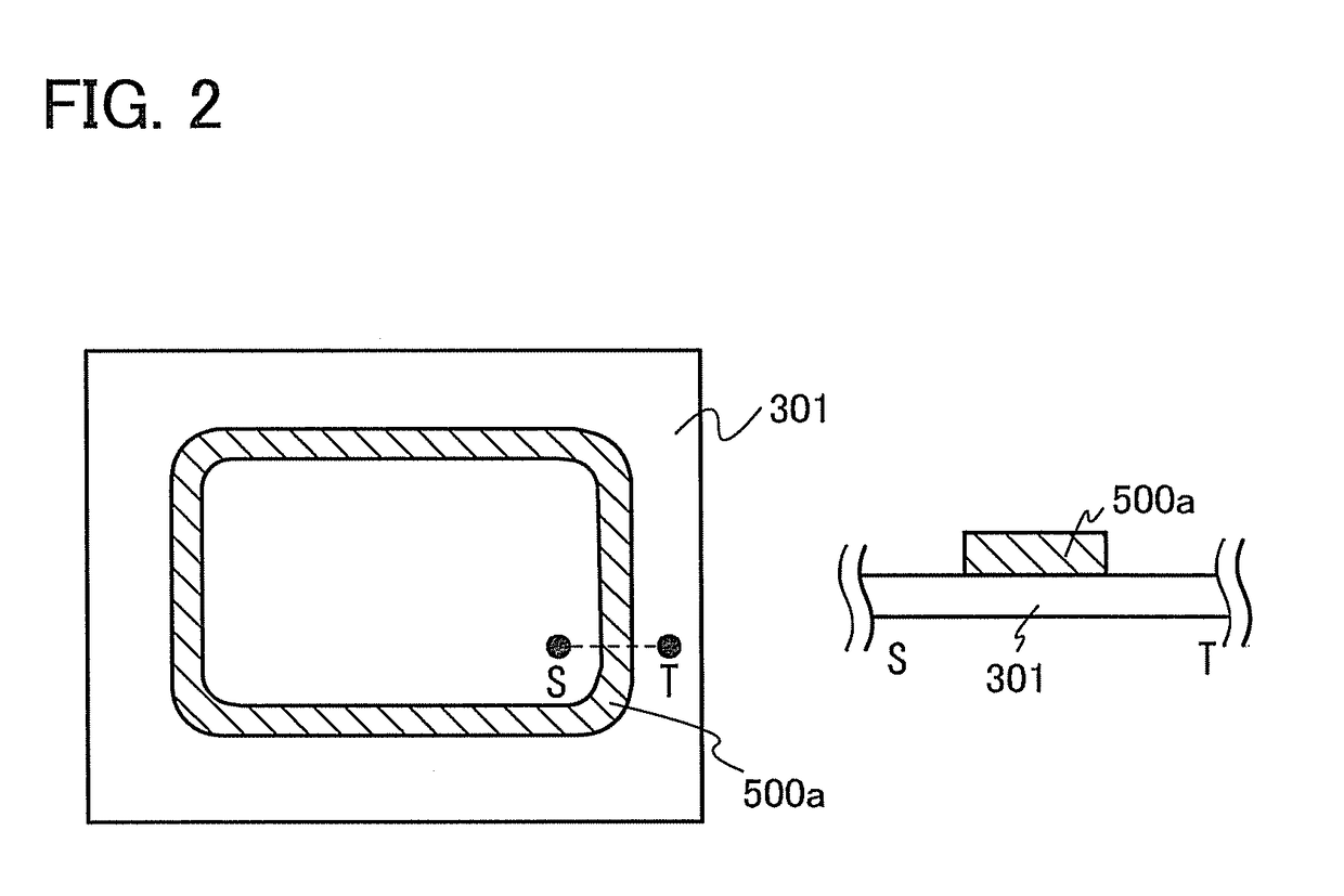
[0038]In this embodiment, a method of manufacturing a sealed body according to one embodiment of the present invention will be described. A method of manufacturing a sealed body 161 in FIGS. 1A to 1C will be described with reference to FIG. 2, FIGS. 3A to 3D, FIGS. 4A to 4D, FIGS. 5A to 5D, and FIGS. 6A to 6C.

(Structure of Sealed Body)

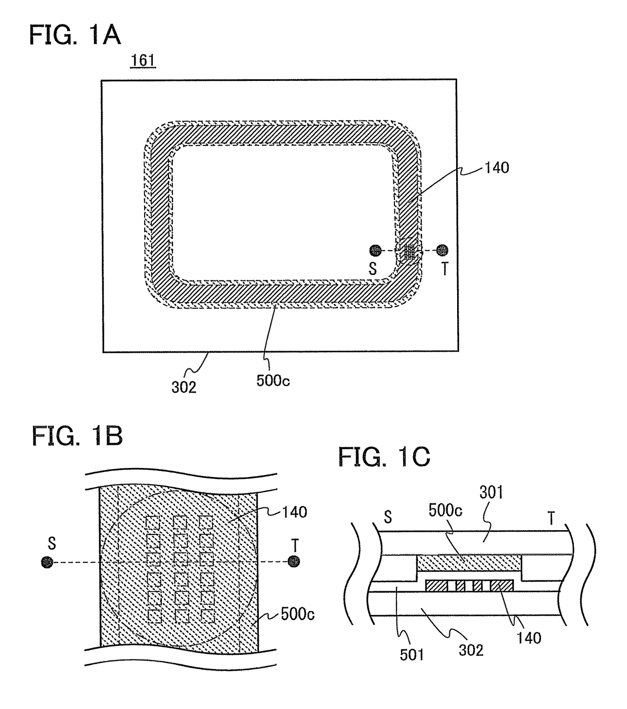
[0039]The sealed body 161 includes a first substrate 301, a second substrate 302, a frit glass layer 500c, a reflective layer 140, and an inorganic insulating layer 501. FIG. 1A is a top view of the sealed body 161. FIG. 1B is a top view in which part of the reflective layer 140 is enlarged, and FIG. 1C is a cross-sectional view taken along dotted line S-T in FIG. 1B. Note that double wave lines in FIGS. 1B and 1C show that some components are not illustrated here.

[0040]In this specification, a frit glass which has been applied as a frit glass paste to a substrate is defined as a frit glass layer 500a, a frit glass obtained by baking the frit glass lay...

embodiment 2

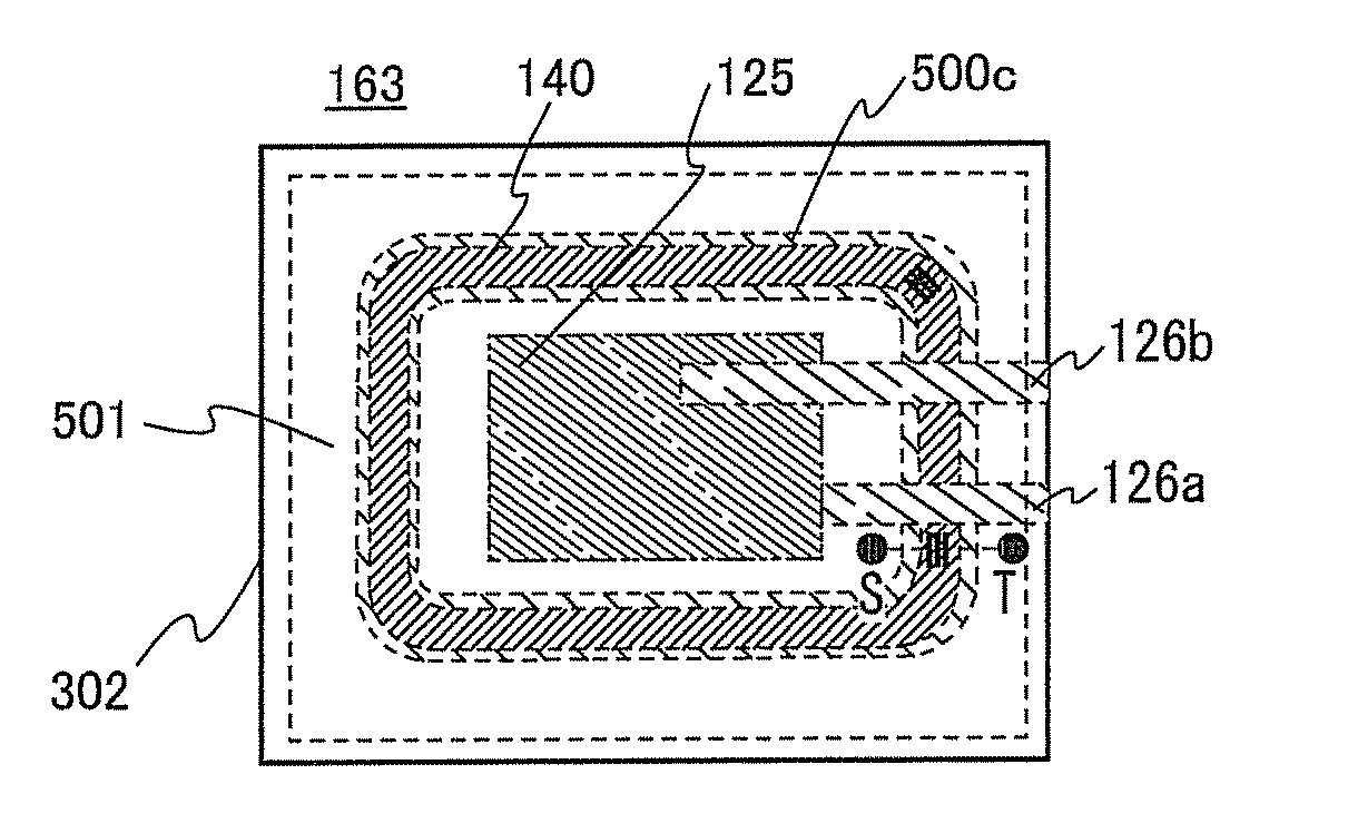
[0065]In this embodiment, a method of manufacturing a light-emitting device according to one embodiment of the present invention will be described. A method of manufacturing a light-emitting device 163 in FIGS. 7A to 7C will be described with reference to FIGS. 8A to 8C and FIGS. 9A to 9C.

(Structure of Light-Emitting Device)

[0066]The light-emitting device 163 includes the first substrate 301, the second substrate 302, the fit glass layer 500c, the reflective layer 140, the inorganic insulating layer 501, an organic EL element 125, a terminal 126a, and a terminal 126b. FIG. 7A is a top view of the light-emitting device 163. FIG. 7B is a top view in which part of the reflective layer 140 is enlarged, and FIG. 7C is a cross-sectional view taken along dotted line S-T in FIG. 7B. Note that double wave lines in FIGS. 7B and 7C show that some components are not illustrated here.

[0067]In this specification, a frit glass which has been applied as a frit glass paste to a substrate is defined ...

embodiment 3

[0092]In this embodiment, one mode of an organic EL element that can be used in a light-emitting device according to one embodiment of the present invention will be described with reference to FIG. 10A.

[0093]In this embodiment, an organic EL element 100 includes a first electrode 101, a light-transmitting conductive layer 103, an organic EL layer 200, and a second electrode 102. The light-transmitting conductive layer 103 is in contact with the first electrode 101. Note that in this embodiment, the following description will be made on the assumption that the first electrode 101 and the light-transmitting conductive layer 103 function as an anode and the second electrode 102 functions as a cathode. In other words, the following description will be made on the assumption that light emission can be obtained when voltage is applied between the first electrode 101 and the second electrode 102 such that the potential of the first electrode 101 is higher than that of the second electrode ...


PUM

PropertyMeasurementUnit
wavelengthaaaaaaaaaa
thicknessaaaaaaaaaa
thicknessaaaaaaaaaa

Abstract

Methods of manufacturing a sealed body and a light-emitting device with high airtightness in which generation of a crack in a substrate and a frit glass in an overlap region where laser light irradiation is started and ended is prevented are provided. A high-reflectivity region having high reflectivity with respect to laser light and a low-reflectivity region having lower reflectivity than the high-reflectivity region are provided in a region which overlaps with the frit glass and is over a substrate facing a substrate on which the frit glass is formed. When scanning with laser light is started from the low-reflectivity region, a crack is less likely to be generated in the frit glass.

Description

BACKGROUND OF THE INVENTION[0001]1. Field of the Invention[0002]The present invention relates to methods of manufacturing a sealed body and a light-emitting device that can be protected from impurities from the outside.[0003]2. Description of the Related Art[0004]Frit glass sealing is known as a technique of sealing a space formed by two bonded glass substrates. A sealed body using frit glass sealing has high airtightness, and is applied to an organic electroluminescence (hereinafter referred to as EL) display device, a liquid crystal display device, a plasma display device, and the like.[0005]Frit glass sealing is used particularly in an organic EL display device so that reliability of an organic EL element is improved. This is because reliability of the organic EL element is rapidly reduced when an organic EL layer and electrodes between which the organic EL layer is interposed are exposed to moisture or oxygen. As a sealing technique using frit glass for preventing exposure of an...

Claims


Application Information

Patent Timeline
Patent Type & Authority Patents(United States)
IPC IPC(8): H01L33/00H01L51/52
CPCH01L33/0095H01L51/5246H10K50/8426H05B33/04H10K71/00
Inventor SHIMOMURA, AKIHISA
Owner SEMICON ENERGY LAB CO LTD
Why Eureka
Try Eureka