Rotating pumping apparatus with seal mechanism
a sealing mechanism and rotating pumping technology, which is applied in the direction of braking systems, machines/engines, braking components, etc., can solve the problems of increasing the possibility of grease leakage into the brake fluid circuit, leaking grease between the oil seal and the shaft, etc., to facilitate the keeping of lubricating grease, increase the length, and the viscosity is higher
- Summary
- Abstract
- Description
- Claims
- Application Information
AI Technical Summary
Benefits of technology
Problems solved by technology
Method used
Image
Examples
first embodiment
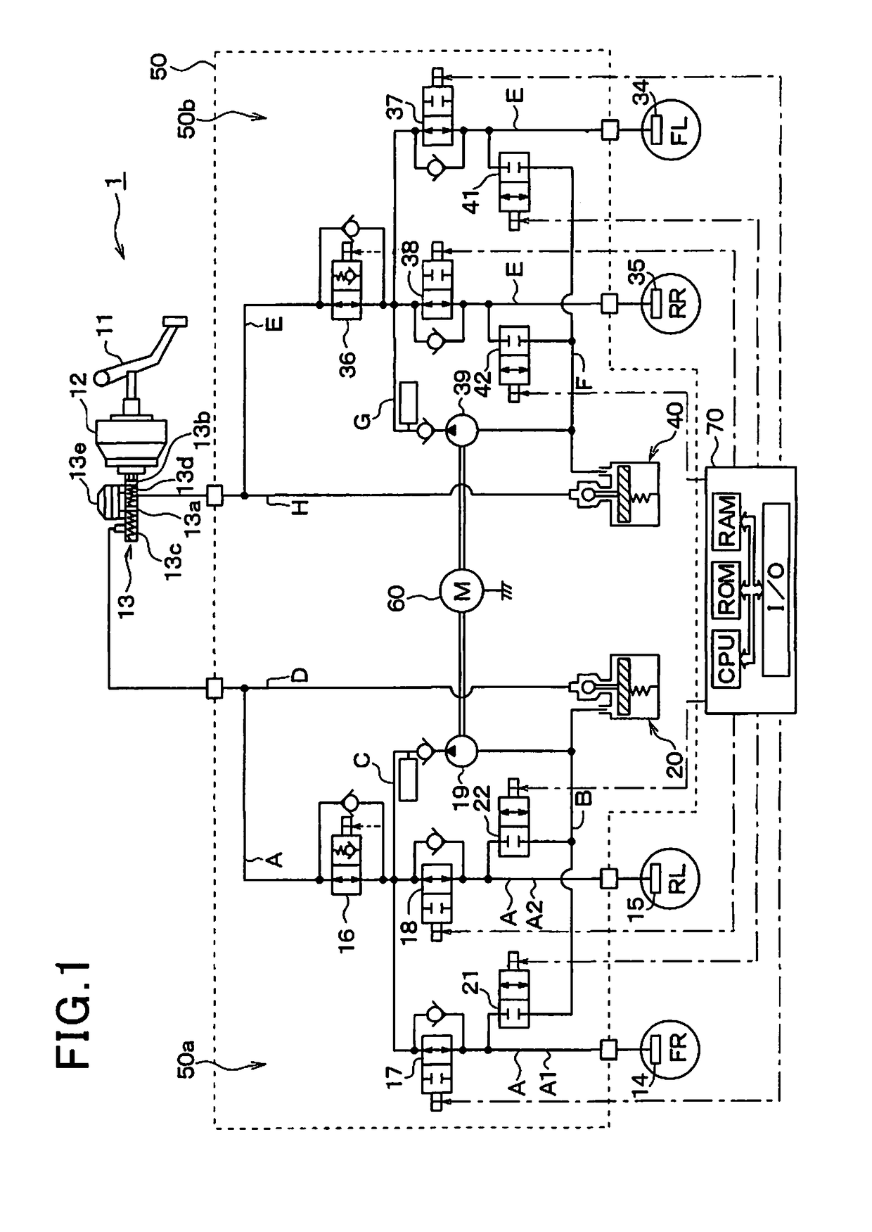
[0032]Referring to FIG. 1, there is shown an automotive brake system equipped with a rotating pumping apparatus according to the first embodiment of the invention. The brake system, as referred to herein, is used with a front-wheel-drive vehicle equipped with a so-called diagonal split system which includes two brake hydraulic circuits one of which controls the right front and the left rear wheel and the other of which controls the left front and the right rear wheel, but may be used with a front / rear split system.
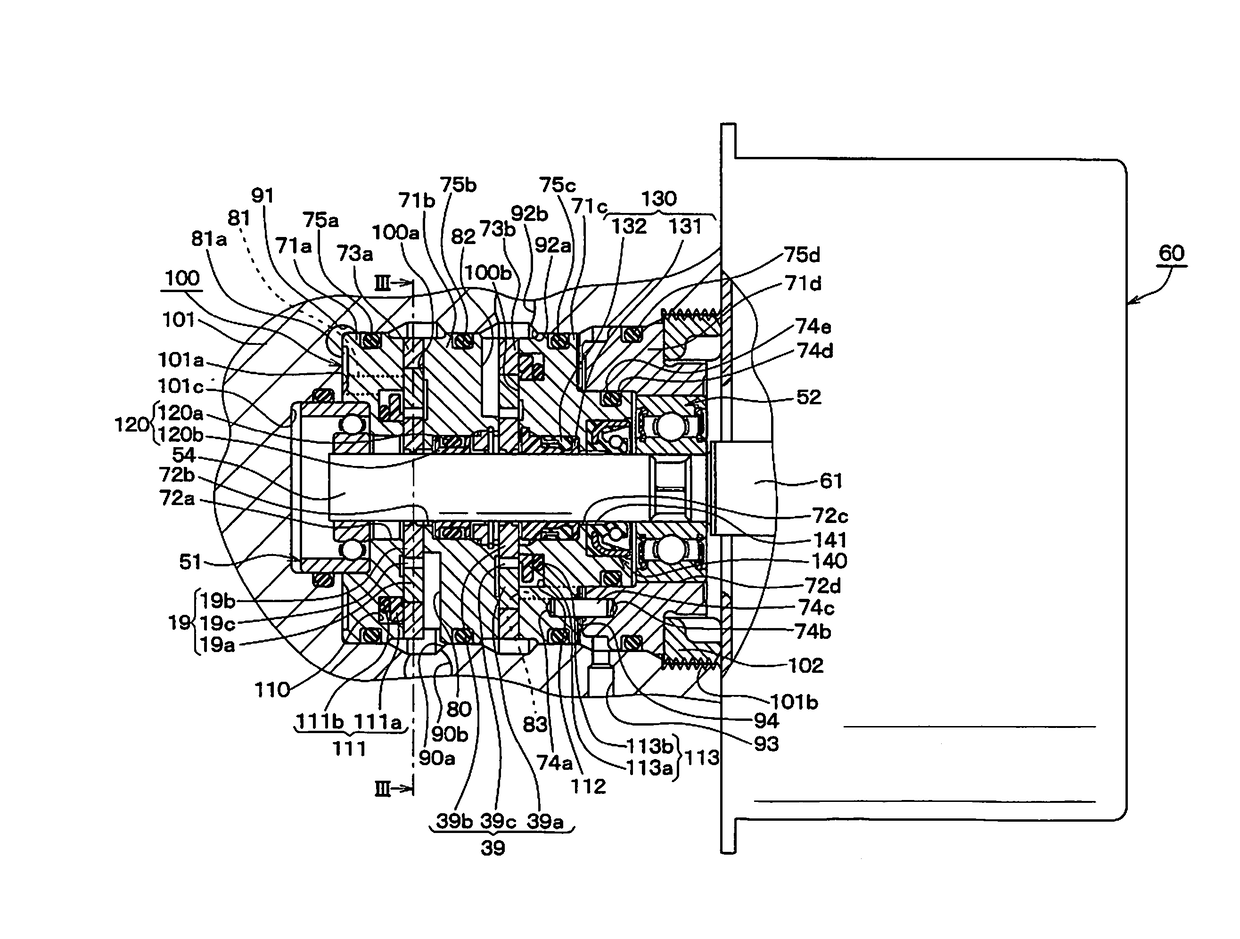
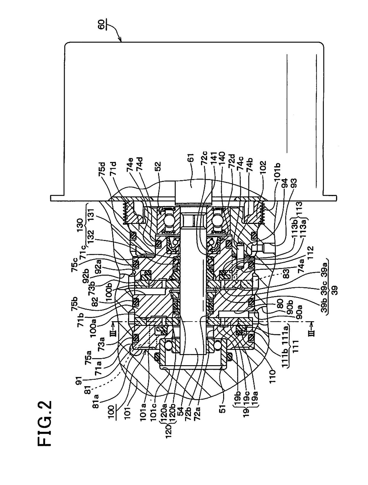
[0033]The brake system includes a brake device 1 which is equipped with a brake pedal 11 (i.e., a brake actuating member) to be depressed by a vehicle occupant or driver for applying the brakes to the vehicle, a brake booster 12, a master cylinder 13, wheel cylinders 14, 15, 34, and 35, and a brake pressure control actuator 50. The actuator 50 has a brake ECU (Electronic Control Unit) 70 installed therein. The brake ECU 70 works to control the braking force, as developed b...
second embodiment
[0108]The second embodiment will be described below which is different only in layout of the hydraulic grooves 131i of the pump body 100 from the first embodiment. Other arrangements of the pump body 100 are identical with those in the first embodiment, and explanation thereof in detail will be omitted here.
[0109]The resinous ring 131, as illustrated in FIG. 8, has formed in the end surface 131h facing the oil seal 140 two hydraulic grooves 131i which are identical in structure with those in the first embodiment. The hydraulic grooves 131i are diametrically opposed to each other, that is, located at an interval of 180° away from each other in the circumferential direction of the resinous ring 131.
[0110]Use of the two hydraulic grooves 131i provides the same beneficial advantages as described in the first embodiment, but the alignment of the outer end of one of the hydraulic grooves 131i which opens on the outer periphery of the resinous ring 131 with one of the slits 132e in the rad...
third embodiment
[0112]The third embodiment will be described below which is different only in configuration of the hydraulic grooves 131i of the pump body 100 from the first embodiment. Other arrangements of the pump body 100 are identical with those in the first embodiment, and explanation thereof in detail will be omitted here.
[0113]The resinous ring 131 has formed in the end surface 131h facing the oil seal 140 four hydraulic grooves 131i each of which extends straight from the center hole (i.e., the inner space) of the resinous ring 131 to the outer periphery (i.e., an outer circumferential surface) of the resinous ring 131 in the radial direction of the resinous ring 131 (i.e., the seal ring 130). The hydraulic grooves 131i are arranged at a regular or equal interval away from each other in the circumferential direction of the resinous ring 131. Each of the outer ends of the hydraulic grooves 131i which opens on the outer periphery of the resinous ring 131 is misaligned with, that is, offset f...
PUM
 Abstract
Description
Claims
Application Information
 - R&D
- Intellectual Property
- Life Sciences
- Materials
- Tech Scout
- Unparalleled Data Quality
- Higher Quality Content
- 60% Fewer Hallucinations
Browse by: Latest US Patents, China's latest patents, Technical Efficacy Thesaurus, Application Domain, Technology Topic, Popular Technical Reports.
© 2025 PatSnap. All rights reserved.Legal|Privacy policy|Modern Slavery Act Transparency Statement|Sitemap|About US| Contact US: help@patsnap.com


