Induction motor control apparatus and induction motor control method
a technology of induction motor and control apparatus, which is applied in the direction of electric generator control, dynamo-electric converter control, dynamo-electric gear control, etc., can solve the problem that the torsional vibration of the drive shaft cannot be suppressed
- Summary
- Abstract
- Description
- Claims
- Application Information
AI Technical Summary
Benefits of technology
Problems solved by technology
Method used
Image
Examples
first embodiment
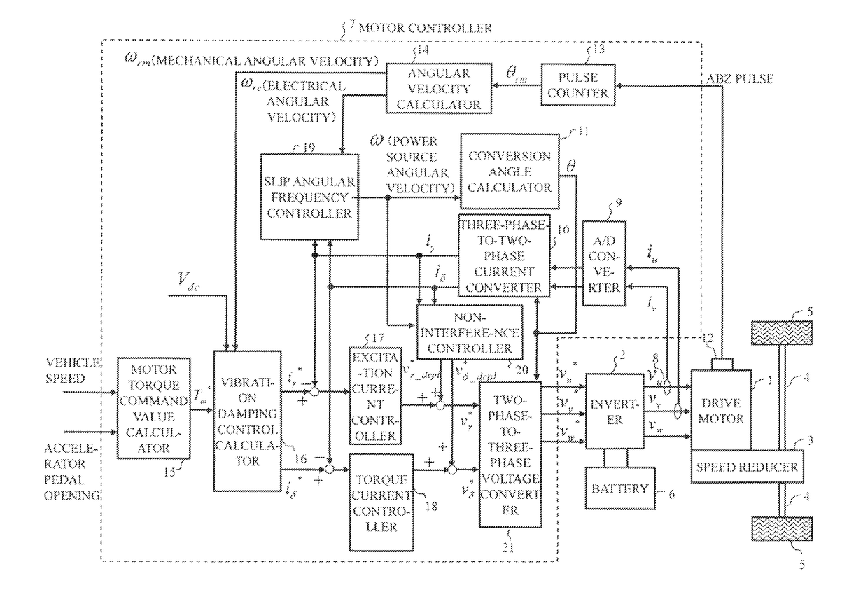
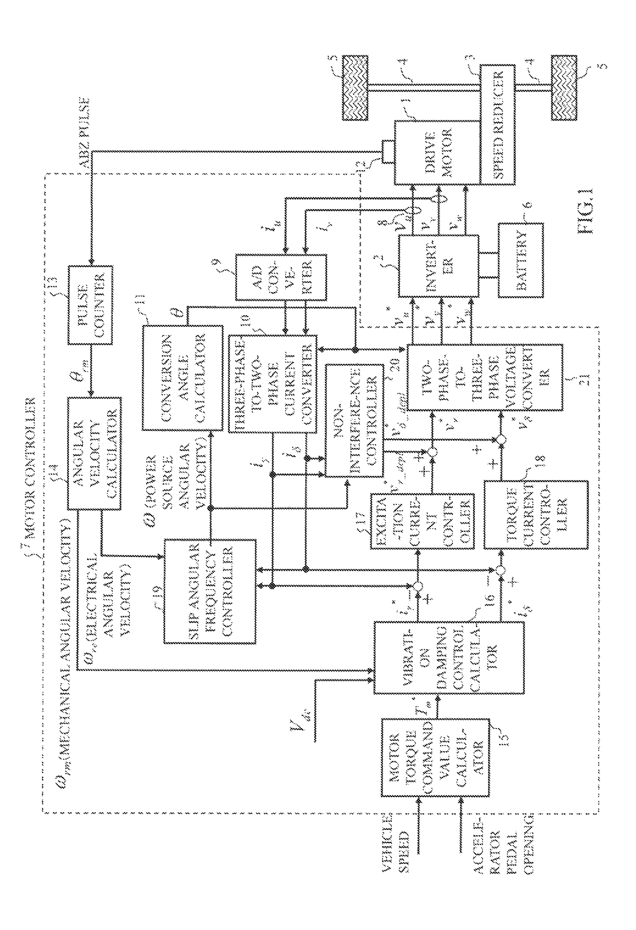
[0022]FIG. 1 is a block diagram showing a configuration of an induction motor control apparatus in a first embodiment. This induction motor control apparatus is, for example, applied to an electric vehicle. A configuration example applied to an electric vehicle is shown in FIG. 1. It should be noted that application to vehicles other than electric vehicles, such as hybrid vehicles and fuel cell vehicles, is also possible.
[0023]A motor controller 7 receives signals of various vehicle variables such as a vehicle speed, an accelerator pedal opening, a rotor position signal and a current flowing in a drive motor 1 in the form of digital signals as inputs. A motor controller 7 generates a PWM signal for controlling the drive motor 1 in accordance with various vehicle variables and generates a drive signal for an inverter 2 through a drive circuit in accordance with this PWM signal.
[0024]The inverter 2 includes two pairs of switching elements (power semiconductor elements such as IGBTs an...
second embodiment
[0096]When a current response is sufficiently faster than a rotor magnetic flux response, current response estimation / calculation processing performed in the magnetic flux estimator 23 can be omitted.
[0097]FIG. 8 is a block diagram showing a detailed configuration of a magnetic flux estimator 23 in a second embodiment. The magnetic flux estimator 23 of the second embodiment includes a magnetic flux response calculator 61 and a multiplier 62 and calculates a first torque command value T1* and a rotor magnetic flux estimated value φ^ by the following equations (28), (29). KT denotes a coefficient determined by parameters of an induction motor and τφ denotes a time constant of a rotor magnetic flux response.
[Equation 28]
T1*=KT^{circumflex over (φ)}·iδ1* (28)
[Equation 29]
[0098]ϕ^=Mτϕ*s+1·iγ1*(29)
[0099]As described above, also in an induction motor control apparatus in the second embodiment, the torsional vibration of a drive shaft of a vehicle can be suppressed without being affected...
third embodiment
[0100]When an induction motor generates a torque in a state of zero rotor magnetic flux, a response delay of torque generation occurs due to a delay of a rotor magnetic flux response. In an induction motor control apparatus of a third embodiment, a fixed amount of the rotor magnetic flux is generated in advance before a motor torque command value is input.
[0101]FIG. 9 is a block diagram showing a detailed configuration of a magnetic flux estimator 23 in a third embodiment. The magnetic flux estimator 23 of the third embodiment includes a magnetic flux response calculator 71, a multiplier 72, a subtractor 73 and an adder 74 and calculates a first torque command value T1* and a rotor magnetic flux estimated value φ^ by the following equations (30), (31). KT denotes a coefficient determined by parameters of an induction motor and τφ denotes a time constant of a rotor magnetic flux response. Further, iγ1 . . . offset denotes a γ-axis current offset value input in advance.
[Equation 30]
T1...
PUM
 Abstract
Description
Claims
Application Information
 - R&D
- Intellectual Property
- Life Sciences
- Materials
- Tech Scout
- Unparalleled Data Quality
- Higher Quality Content
- 60% Fewer Hallucinations
Browse by: Latest US Patents, China's latest patents, Technical Efficacy Thesaurus, Application Domain, Technology Topic, Popular Technical Reports.
© 2025 PatSnap. All rights reserved.Legal|Privacy policy|Modern Slavery Act Transparency Statement|Sitemap|About US| Contact US: help@patsnap.com


