
Substrate liquid treatment apparatus and substrate liquid treatment method

a substrate liquid and treatment apparatus technology, applied in the direction of electrical apparatus, chemistry apparatus and processes, cleaning processes and apparatuses, etc., can solve the problems of affecting the productivity, extending the processing time, adversely affecting the device pattern formed on the wafer w, etc., to reduce the amount of cleaning liquid reaching the notch part, prevent the penetration of cleaning liquid into the front surface of the substrate, and shorten the drying time

Active Publication Date: 2017-02-14
TOKYO ELECTRON LTD
View PDF6 Cites 0 Cited by
  • Summary
  • Abstract
  • Description
  • Claims
  • Application Information

AI Technical Summary

Benefits of technology

The present invention provides a technology for drying a substrate without causing defects or extending the processing time. By using a purge gas to promote drying and prevent contamination, and a tubular member to prevent adhesion of the cleaning liquid to the substrate holding unit and contamination of the tubular member, the substrate can be dried quickly and without the need for additional steps. This results in a faster treatment time and prevents defects caused by the penetration of the cleaning liquid into the front surface of the substrate.

Problems solved by technology

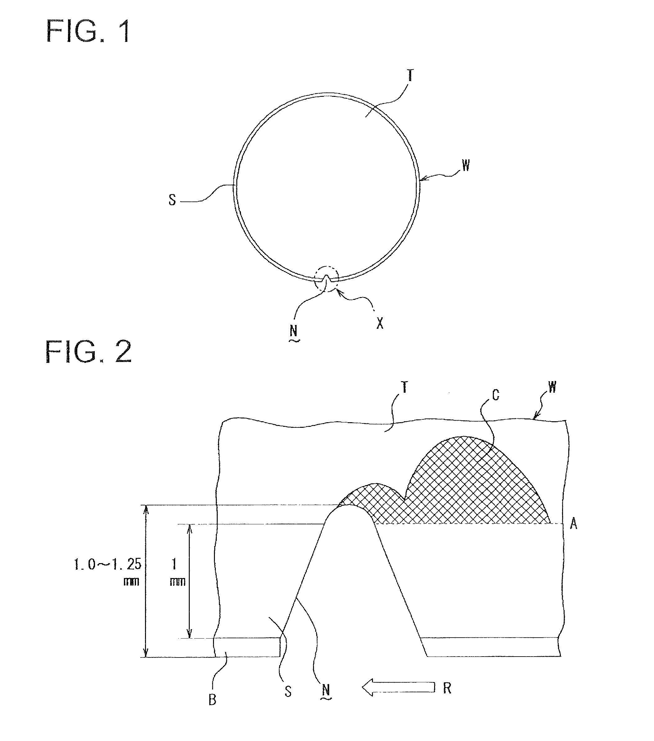
The cross-hatched region C is located in the device region of the wafer W and a defect existing in the device region can adversely affect the device patterns formed on the wafer W.
However, setting the drying step recipe in multiple stages leads to extension of the processing time and that adversely affects the productivity.

Method used


Image

  • Substrate liquid treatment apparatus and substrate liquid treatment method
  • Substrate liquid treatment apparatus and substrate liquid treatment method
  • Substrate liquid treatment apparatus and substrate liquid treatment method

Examples


Embodiment Construction

[0037]The substrate liquid treatment apparatus in one embodiment of the present invention may be configured to perform a prescribed liquid treatment to a substrate by supplying a treatment liquid (e.g., cleaning liquid for cleaning a wafer, resist solution for forming a resist film, anti-reflection film forming liquid, developing solution for developing patterns after the exposure, etc.) to the front surface of the substrate. The substrate liquid treatment apparatus comprises a configuration for cleaning the back surface of the substrate in order to prevent the treatment liquid used for the liquid treatment from remaining on the back surface of the wafer, or to prevent generation of particles from the remaining treatment liquid. The embodiment described below relates to a configuration for preventing the occurrence of a defect (defective part) in a region on the substrate's front surface in the vicinity of the notch part after the substrate back surface cleaning, and for drying the ...


PUM


Abstract

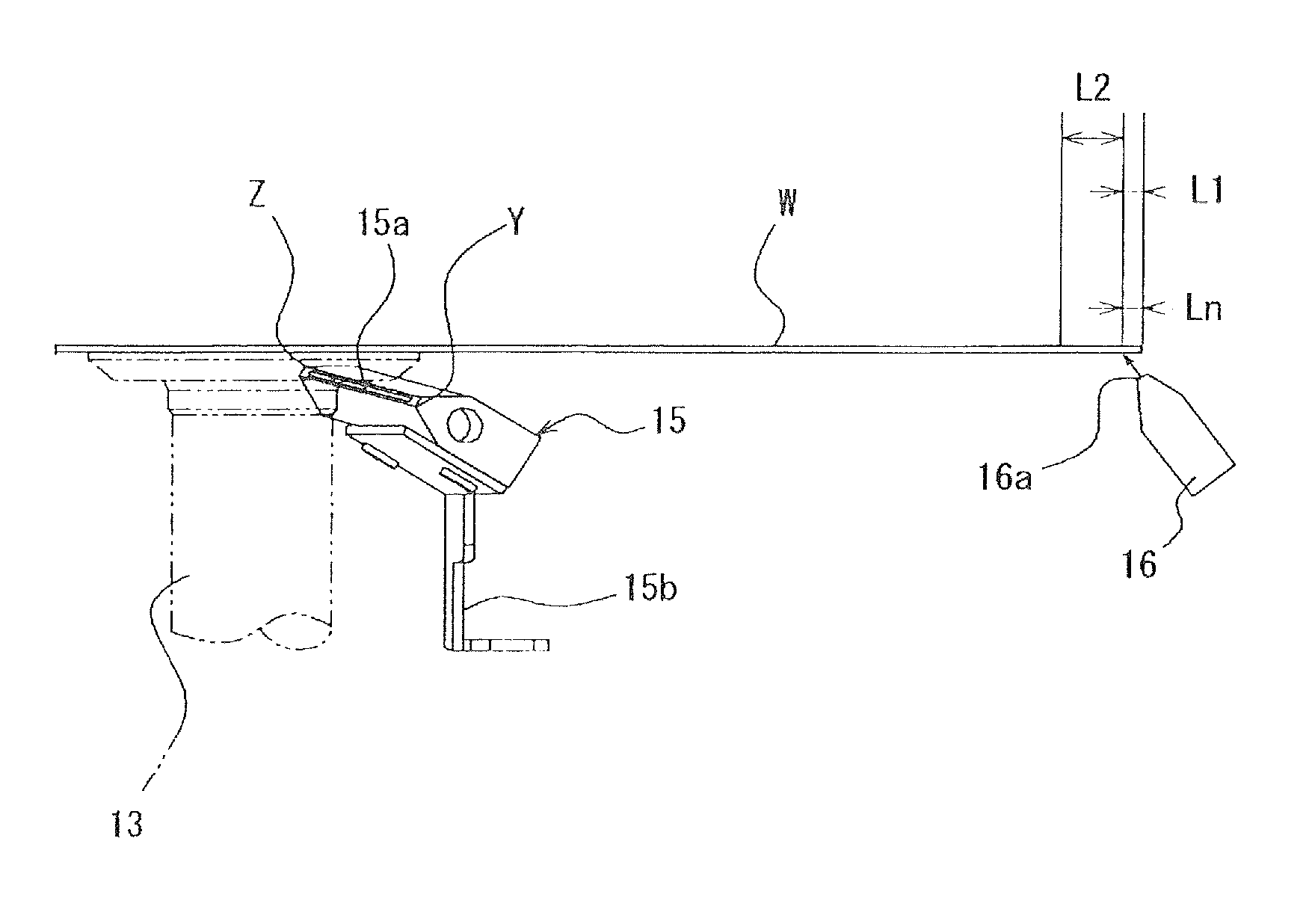
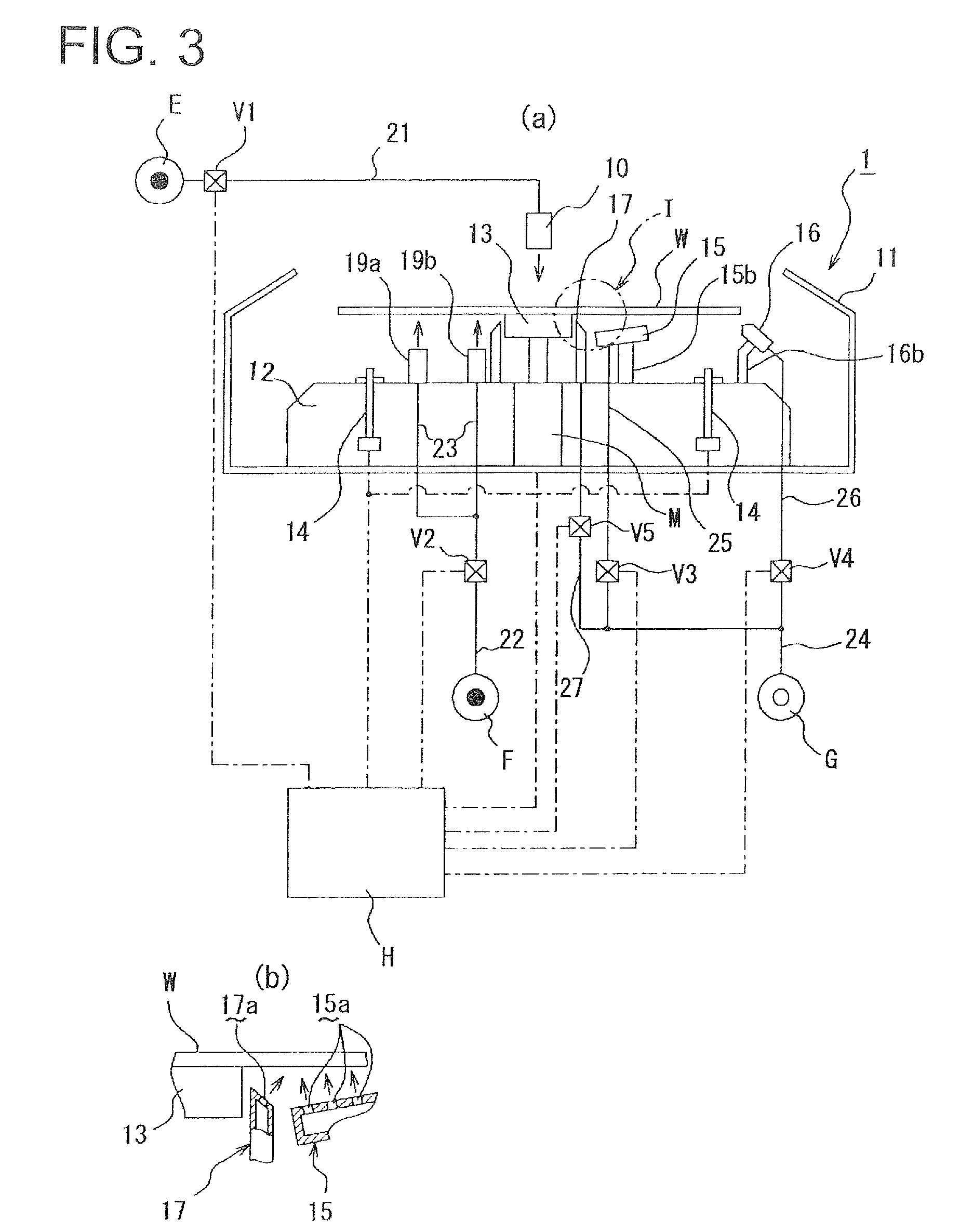
A substrate liquid treatment apparatus comprises a chuck (13) that holds and rotates a wafer, a back surface purging nozzle (15) that discharges a purge gas toward the back surface of the wafer, and a periphery purging nozzle 16 that discharges the purge gas onto the back surface of the wafer. The back surface purging nozzle has a slit-like opening part extending from a central side to a peripheral side of the substrate in a plan view. Vertical distance between the slit-like opening part and the substrate held by the substrate holding unit increases as approaching an end of the opening part on the central side of the substrate. The periphery purging nozzle discharges the purge gas, toward a central part of the substrate, toward a region on the back surface of the substrate, which region is located radially outside an end of the slit-like opening part of the back surface purging nozzle and radially inside an peripheral edge of the substrate.

Description

TECHNICAL FIELD[0001]The present invention relates to a substrate liquid treatment apparatus and a substrate liquid treatment method. In particular, the present invention relates to a technology for drying a cleaning liquid that was used in a back surface cleaning step for a substrate such as a glass substrate for a semiconductor wafer or a photomask, a glass substrate for a liquid crystal display device, a substrate for an optical disc, a substrate for bonding, and so forth (hereinafter collectively referred to simply as a “substrate”). Such a back surface cleaning process can be conducted together with various types of liquid treatment processes such as a coating film formation, a pattern development, a front / back surface brush cleaning and a chemical solution cleaning.BACKGROUND ART[0002]A photolithography process is conducted by using various types of liquid treatment units such as a coating unit for performing a film formation to a substrate by supplying a coating liquid to a s...

Claims


Application Information

Patent Timeline
Patent Type & Authority Patents(United States)
IPC IPC(8): B08B5/02B08B5/00H01L21/67
CPCH01L21/67051B08B5/00B08B5/02B08B5/023H01L21/67028H01L21/67034H01L21/6708
Inventor FUKUDA, MASAHIROKUBO, AKIHIROYAMAMOTO, TAROYADA, KENZIOOKOUCHI, ATSUSHI
Owner TOKYO ELECTRON LTD
Learn More