Manufacturing method of radiator-integrated substrate and radiator-integrated substrate

a technology of radiator and integrated substrate, which is applied in the direction of manufacturing tools, soldering apparatus, and semiconductor/solid-state device details, etc., can solve the problems of reducing the heat radiation property and likely warpage of the base plate, and achieve excellent strength and heat radiation property, the effect of costing raw materials

Active Publication Date: 2016-10-18
NIPPON LIGHT METAL CO LTD +1
View PDF15 Cites 5 Cited by
  • Summary
  • Abstract
  • Description
  • Claims
  • Application Information

AI Technical Summary

Benefits of technology

The present invention provides a way to make a radiator-integrated substrate that saves money on raw materials and processing costs while also reducing warping. In addition, the substrate is stronger and has better heat radiation properties.

Problems solved by technology

Since soldering of the base plate, the electronic component and so on to the metal-ceramic insulating substrate is performed by heating, warpage of the base plate is likely to occur due to a difference in thermal expansion coefficient between bonded members during the soldering.
Further, the heat generated from the electronic component and so on is released to air, cooling water or the like by the heat radiation fin or the cooling jacket (radiator) via the metal-ceramic insulating substrate, the solder and the base plate, so that when warpage occurs in the base plate, the clearance when attaching the heat radiation fin or the cooling jacket to the base plate increases, thus extremely decreasing the heat radiation property.

Method used


Image

  • Manufacturing method of radiator-integrated substrate and radiator-integrated substrate
  • Manufacturing method of radiator-integrated substrate and radiator-integrated substrate
  • Manufacturing method of radiator-integrated substrate and radiator-integrated substrate

Examples


examples

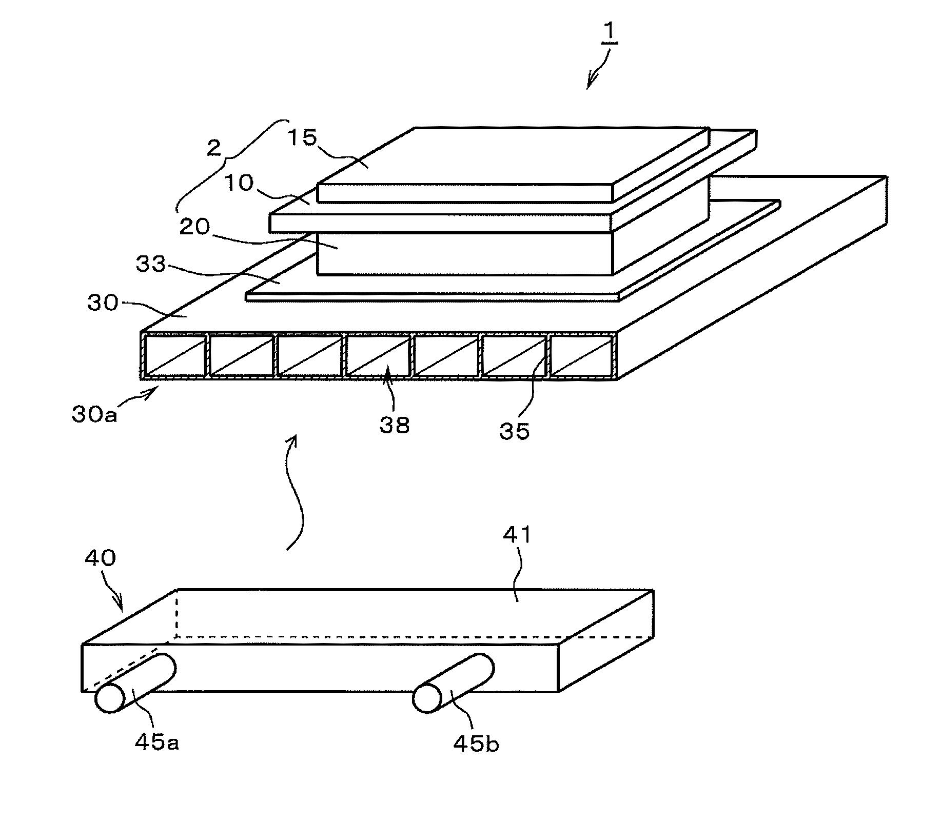
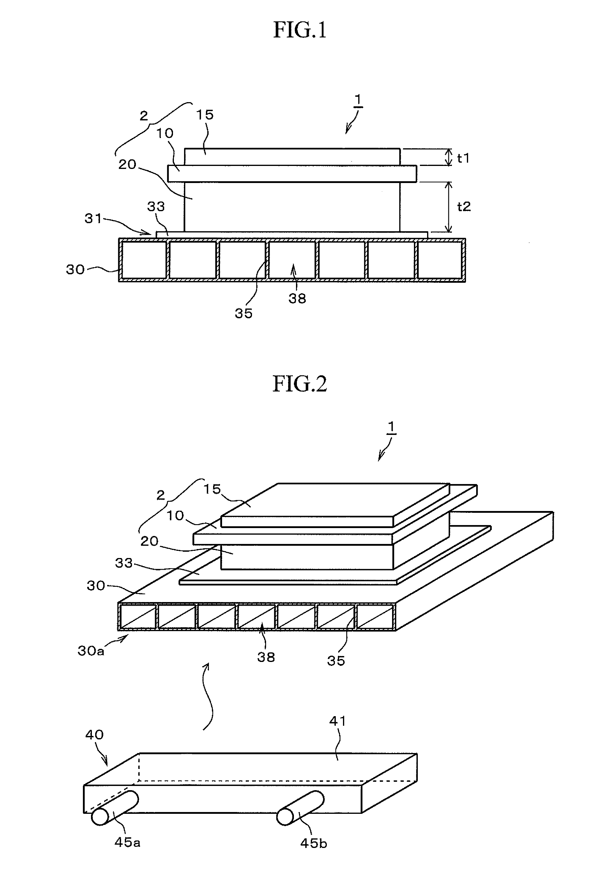
[0050]A test was carried out in which a metal-ceramic bonded substrate “ALMIC” (registered trademark) made by molten-metal bonding (direct-bonding) an aluminum alloy on both surfaces of an AlN substrate and a porous pipe (radiator) were brazed together using jigs having a concave R surface and a convex R surface to manufacture a radiator-integrated substrate.

[0051]First of all, radiators composed of porous pipes (material: made of an aluminum alloy with an alloy number A6063, solidus temperature: 615° C.) of two sizes such as a width of 127 mm×a length of 140 mm×a thickness of 8 mm (Invention Examples 1 to 10, Comparative Examples 1 to 5, Comparative Examples 8 to 11), and a width of 150 mm×a length of 140 mm×a thickness of 10 mm (Invention Example 11, Comparative Examples 6, 7) were prepared. In each of the radiators composed of porous pipes, a plurality of pipes of refrigerant flow paths were consecutively arranged as illustrated in FIG. 1, and a groove width W (width of pipe) of ...


PUM

PropertyMeasurementUnit
surface pressureaaaaaaaaaa
thickness t2aaaaaaaaaa

Abstract

A metal circuit board and a metal base plate are bonded to a ceramic substrate to form a metal-ceramic bonded substrate, then the metal base plate is arranged on one surface of the radiator via a brazing material with the metal base plate overlapping with the one surface of the radiator, a jig having a concave R surface is arranged on another surface of the radiator with the jig butting against the another surface of the radiator, a jig having a convex R surface protruding toward the metal-ceramic bonded substrate is brought into contact with another surface of the metal circuit board, and the metal-ceramic bonded substrate and the radiator are heat-bonded while they are pressurized by the radiator side jig and the metal-ceramic bonded substrate side jig, wherein a curvature radius R (mm) of the convex R surface and the concave R surface is 6500≦R≦surface pressure (N / mm2)×2000+12000.

Description

TECHNICAL FIELD[0001]The present invention relates to a metal-ceramic bonded substrate and, in particular, to a manufacturing method of a radiator-integrated substrate and a radiator-integrated substrate in which a metal circuit board and a metal base plate each made of aluminum or an aluminum alloy are bonded to both surfaces of a ceramic substrate respectively and a radiator is bonded to a surface of the metal base plate where the ceramic substrate is not bonded.[0002]This application is based upon and claims the benefit of priority of the prior Japanese Patent Application No. 2012-061603, filed in Japan on Mar. 19, 2012, the entire contents of which are incorporated herein by reference.BACKGROUND ART[0003]In a conventional power module used to control a large current, for example, in an electric vehicle, an electric train, a machine tool or the like, a metal-ceramic insulating substrate is fixed on one surface of a metal plate or a composite material called a base plate by solder...

Claims


Application Information

Patent Timeline
Patent Type & Authority Patents(United States)
IPC IPC(8): H05K1/02B23K1/19H05K1/05B23K1/00H01L21/48C04B35/645C04B37/02H05K13/04H01L23/373H05K3/00H01L23/473H05K1/03
CPCH05K1/021B23K1/0008B23K1/0012B23K1/0016B23K1/19C04B35/645C04B37/021H01L21/4882H01L23/3735H05K1/0271H05K1/05H05K13/0465C04B2237/366C04B2237/368C04B2237/402C04B2237/66C04B2237/704H01L23/473H01L2924/0002H05K1/0306H05K3/0061H05K2203/0278H01L2924/00
Inventor HORI, HISASHIKOKUBO, TAKANORIOSANAI, HIDEYOCHIHARA, KUNIHIKO
Owner NIPPON LIGHT METAL CO LTD
Why Eureka
Try Eureka