Punching sheet-type flange

a flange and sheet-type technology, applied in the direction of fastening means, couplings, mechanical devices, etc., can solve the problems of inconvenient installation, inability to use traditional flanges, and urgent need for flanges suitable for this case, so as to improve assembling efficiency and facilitate assembling and replacement

Active Publication Date: 2016-10-11
ZHEJIANG LINIX MOTOR
View PDF10 Cites 0 Cited by
  • Summary
  • Abstract
  • Description
  • Claims
  • Application Information

AI Technical Summary

Benefits of technology

[0009]The purpose of the invention is to provide a punching sheet-type flange processed by punching processing and then assembled, to solve the difficulty in die casting of flanges having complex structures.
[0015]Preferably, the substrate and the flange sheets are provided with connection holes, and the connection holes on the substrate correspond to those on the flange sheets. Rivets pass through the connection holes to integrally fix the flange sheets and the substrate. The protruded length of two ends of a rivet is short, thus less interference will be caused with the end parts of the connection pieces on both sides, or crew rods are fixed on the connection holes of the substrate and pass through the connection holes. Two ends of one crew rod are connected with the flange sheets on both sides of the substrate, and the end parts of the crew rods are fixed by nuts, in this way, the number of the flange sheets is adjusted conveniently, and the flange sheets may be increased at any time during assembling.
[0016]Preferably, the connection holes and the connection slots are mutually staggered, and a connection hole is arranged between two adjacent connection slots. The staggered arrangement enables the flange sheets to bear uniform stress, and meanwhile, the stress delivered to the flange sheet on the other side by the substrate is relatively uniform, so that the local crack of the flange caused by overlarge stress on a local part may be avoided.
[0020]Preferably, the periphery of the connection slots is of an open structure, and the connection slots are in the shape of dovetail slots. The width of the connection slots on the edge of the flange sheets is smaller than that of the inner side of the connection slots, the inner side edge of the connection slots is an arc, and this arc and the arc of the inner circle of the flange sheets form a concentric structure. The splicing manner of the connection slots of the dovetail slots is axial movement rather than radial movement, so as to ensure that the connection slots will not depart from the flange due to a centrifugal force when rotating. The inner side edge of the connection slots is an arc, so that the annular width of the flange sheets on this part is equal, and the strength of the flange sheets is guaranteed.
[0022]The invention has the following advantages: the substrate combines with the flange sheets to form the flange, the substrate and the flange sheets are formed by punching, the number of the flange sheets is adjustable, flange sheets with a complex structure may be processed to accommodate connection pieces of different structures, and connection by the connection slots enables convenient assembling and replacement and improves the assembling efficiency.

Problems solved by technology

If the thickness of the flange is appropriate, several thin flanges may be installed by overlapping, but this installation manner is not always convenient.
If the end parts of the connection pieces are unsuitable to process connection holes for bolts or unsuitable to fix flanges due to their shape structures, the traditional flanges can not be used.
Therefore, a flange suitable for this case is in urgent need.
However, as some connection pieces have relatively complex structure, the connected flange structures appear different from the traditional flange structures.
It becomes very difficult to process flanges by the traditional die-casting way at this time.
The structure of the flange main body formed by combing multiple sector plates is still a circular structure, and the installation of the flange is still achieved by bolt connection, so this flange is not suitable for connection pieces with non-bolt connection.
The composite members are formed by die-casting and then still connected by blots after spliced, so this flange is not suitable for connection pieces with non-bolt connection.

Method used


Image

  • Punching sheet-type flange
  • Punching sheet-type flange
  • Punching sheet-type flange

Examples


embodiment 1

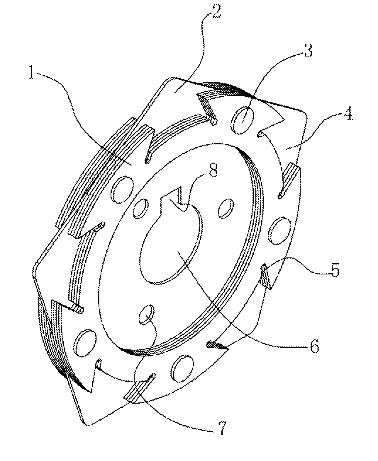
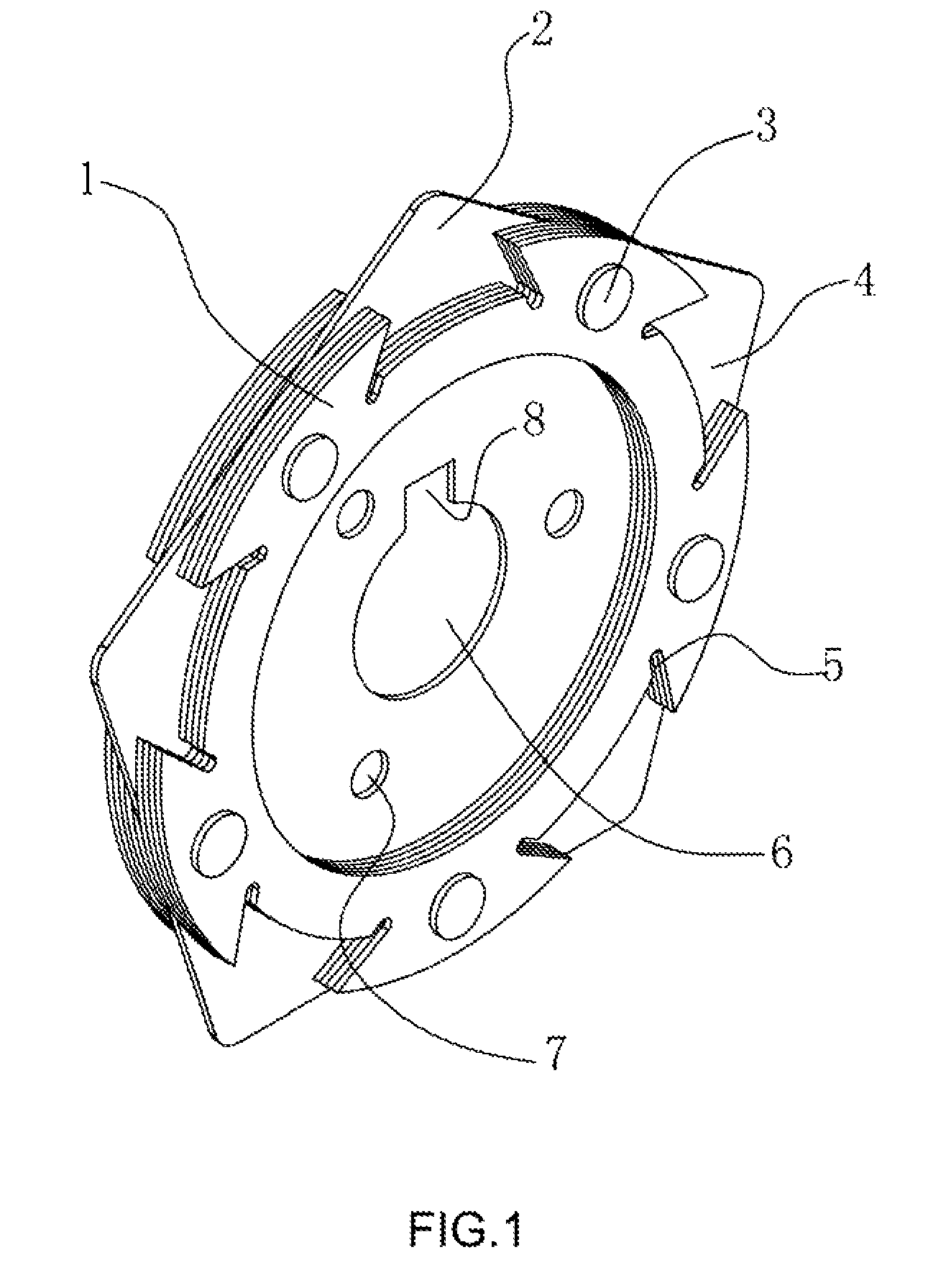
[0028]A punching sheet-type flange (referring to FIG. 1) is provided, comprising a substrate 2 and eight flange sheets 1 fixed with the substrate. The substrate and the flange sheets are of a punching sheet structure and have same thickness. The flange sheets are symmetrically fixed on both sides of the substrate, and four flange sheets are fixed on both sides of the substrate, respectively. The dimension of the substrate is greater than that of the flange sheets. The substrate is pentagonal, and the flange sheets are annular. The middle part of the substrate is provided with an axle hole 6 with a key slot 8, and the substrate is also provided with three fixed holes 7 distributed uniformly and circularly around the axle center of the axle hole. Five connection holes are arranged on the substrate, and each of the connection slots corresponds to one side of the substrate. The flange sheets are provided with connection holes corresponding to those on the substrate. Rivets 3 pass throug...

embodiment 2

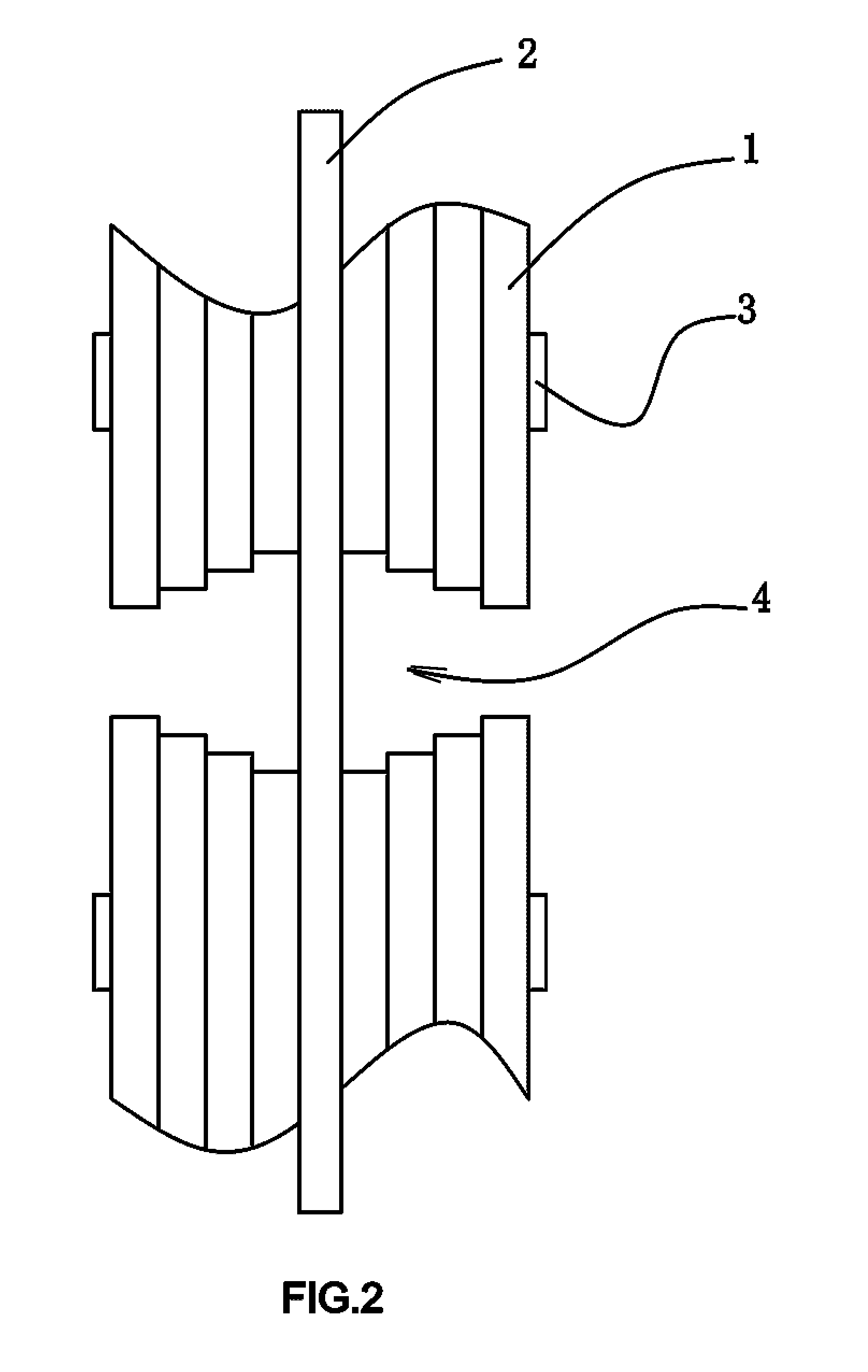
[0030]A punching sheet-type flange (referring to FIG. 2) is provided. Four flange sheets 1 are fixed on both sides of the substrate 2, respectively. Each of the connection slots corresponds to one corner of the substrate, and the connection slots are in the shape of dovetail slots. The width of the connection slots on the edge of the flange sheets is smaller than that of the inner side of the connection slots, the inner side of the connection slots is arc, and this arc and the arc of the inner circle of the flange sheets form a concentric structure. The shape of the connection slots on a same flange sheet is the same, while the shape of the connection slots on the four flange sheets is different, wherein width of the connection slots on a flange sheet on the outmost side of the flange is smallest. The width of a connection slot will be greater if the connection slot is on a flange sheet closer to the substrate. The width of the connection slot close to the substrate from the outer s...

embodiment 3

[0032]A punching sheet-type flange (referring to FIG. 3) is provided. Four flange sheets 1 are symmetrically fixed on both sides of the substrate 2, respectively. The substrate and the flange sheets are integrally fixed by rivets 3. Five open connection slots 4 are arranged on the periphery of the flange sheets. The connection slots are arc-shaped, and this arc and the circular ring of the flange sheets form a concentric structure. The rotation direction of the five connection slots is the same, and each one of the connection slots corresponds to one corner of the substrate, and the open direction of the connection slots on both sides of the substrate is the same. Other structures refer to Embodiment 1.

[0033]During assembling, the end parts of the connection pieces are aligned with the open parts of the connection slots first, and then the connection pieces are made to rotate around the axis of the flange, so that the connecting parts on the end parts of the connection pieces are sc...


PUM


Abstract

A sheet-type flange for transmitting power is formed by a substrate and a multiple of flange sheets. The substrate has a central axle hole with a square key slot and a multiple of fixed holes distributed around the axle hole. The multiple of flange sheets are annular and have connection slots arranged on a periphery of the flange sheets, as well as the multiple of flange sheets are arranged on both sides of the substrate respectively. The substrate and the multiple of flange sheets are fixed together by rivets.

Description

CROSS REFERENCE TO RELATED PATENT APPLICATION[0001]The present application is the national stage of PCT / CN2012 / 075687 filed on May 18, 2012, which claims the priority of the Chinese patent application No. 201110153939.8 filed on Jun. 9, 2011.TECHNICAL FIELD OF THE INVENTION[0002]The invention belongs to the field of transmission connection, particularly relates to a punching sheet-type flange formed by overlapping and fixing punching sheet-structure assemblies for transmission.BACKGROUND OF THE INVENTION[0003]The traditional flanges are mostly processed by die-casting, so they are of integral structures. Even for a weld neck flange, it is also formed by processing two flange assemblies by die-casting and then integrally fixing the two flange assemblies by welding, and such weld neck flange is common in pipe welding.[0004]After a flange is processed, the thickness of the flange is non-adjustable, and each kind of flange has a respective installation thickness. When the connection thi...

Claims


Application Information

Patent Timeline
Patent Type & Authority Patents(United States)
IPC IPC(8): F16B5/00F16D1/033F16D3/79
CPCF16D1/033F16D3/79Y10T403/64F16B2200/50
Inventor RUAN, XIAODING
Owner ZHEJIANG LINIX MOTOR
Why Eureka
Try Eureka