
Liquid crystal display device

a liquid crystal display and display device technology, applied in the direction of liquid crystal compositions, instruments, chemistry apparatus and processes, etc., can solve the problems of reducing the voltage holding ratio (vhr) of the liquid crystal layer, defective display including voids, and techniques that are not substantially different from merely reducing the impurity content, so as to prevent the decrease of the voltage holding ratio (vhr), prevent the increase of the ion density (id), and eliminate the defect of the display

Active Publication Date: 2016-10-11
DIC CORPORATION
View PDF15 Cites 7 Cited by
  • Summary
  • Abstract
  • Description
  • Claims
  • Application Information

AI Technical Summary

Benefits of technology

The solution effectively prevents decreases in voltage holding ratio and ion density, eliminating issues like voids, uneven alignment, and screen burn-in, thereby enhancing the performance and reliability of liquid crystal display devices.

Problems solved by technology

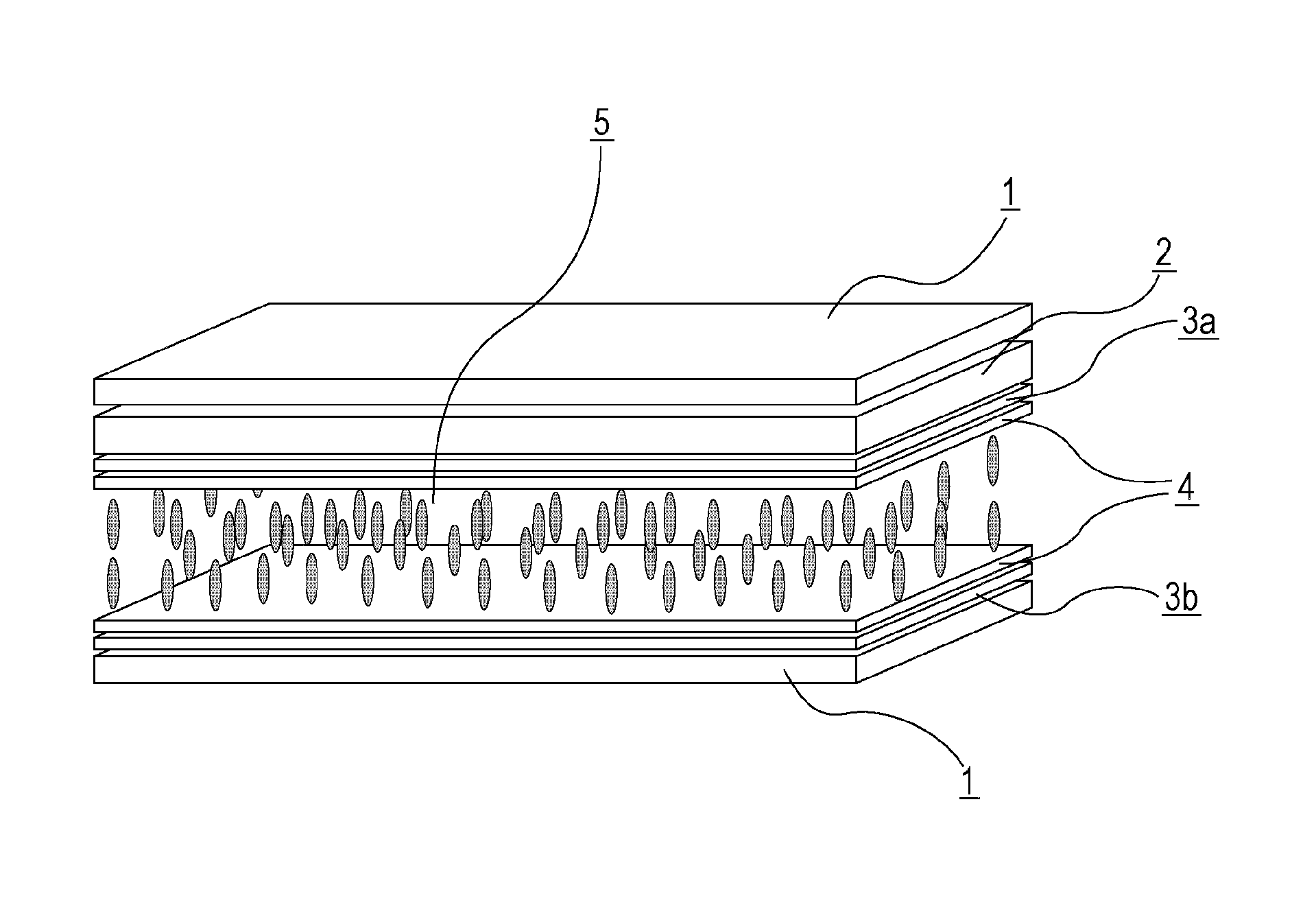
Hence, the color filter layer and the liquid crystal layer are not in a state in which they are completely isolated from each other, and the color filter layer may therefore cause problems owing to impurities which are contained in the color filter layer and which pass through the alignment film and the transparent electrode, such as a decrease in the voltage holding ratio (VHR) of the liquid crystal layer and defective display including voids due to increased ion density (ID), uneven alignment, and screen burn-in.
These techniques, however, are substantially not different from merely reducing the impurity content in a pigment and are insufficient in improvements to overcome defective display even in a current situation in which a technique for purifying pigments has been advanced.
Also in such disclosure, however, the technique is substantially for reducing effects of impurities present in a pigment on the liquid crystal layer, and a direct relationship between the properties of a colorant itself used in the color filter layer, such as a dye or a pigment, and the structure of a liquid crystal material is not considered; thus, problems of defective display in highly-developed liquid crystal display devices have not been overcome.

Method used


Image

  • Liquid crystal display device
  • Liquid crystal display device
  • Liquid crystal display device

Examples


synthesis example 1

Synthesis of Copolymer a

[0241]In a nitrogen flow, 100 parts of xylene was held at 80° C.; and then a mixture of 68 parts of ethyl methacrylate, 29 parts of 2-ethylhexyl methacrylate, 3 parts of thioglycolic acid, and 0.2 parts of a polymerization initiator (“PERBUTYL® O” [active ingredient: t-butyl peroxy-2-ethylhexanoate, manufactured by NOF CORPORATION]) was added dropwise thereto under stirring over 4 hours. After the dropping was completed, 0.5 pats of “PERBUTYL® O” was added thereto every 4 hours, and the resulting product was stirred at 80° C. for 12 hours. After termination of the reaction, xylene was added thereto to adjust the nonvolatile content, thereby producing a xylene solution of a copolymer a with a 50% nonvolatile content.

synthesis example 2

Synthesis of Copolymer b

[0242]In a nitrogen flow, 100 parts of xylene was held at 80° C.; and then a mixture of 66 parts of ethyl methacrylate, 28 parts of 2-ethylhexyl methacrylate, 6 parts of thioglycolic acid, and 0.3 parts of a polymerization initiator (“PERBUTYL® O” [active ingredient: t-butyl peroxy-2-ethylhexanoate, manufactured by NOF CORPORATION]) was added dropwise thereto under stirring over 4 hours. After the dropping was completed, 0.5 pats of “PERBUTYL® O” was added thereto every 4 hours, and the resulting product was stirred at 80° C. for 12 hours. After termination of the reaction, a proper amount of xylene was added thereto to adjust the nonvolatile content, thereby producing a xylene solution of a copolymer b with a 50% nonvolatile content.

synthesis example 3

Synthesis of Polymer A

[0243]Into a flask equipped with a stirrer, a reflux condenser, a nitrogen inlet, and a thermometer, a mixture of 54.5 parts of xylene, 19.0 parts of the copolymer a obtained in Synthesis Example 1, 38.0 parts of the copolymer b, and 7.5 parts of a 20% aqueous solution of polyallylamine (“PAA-05” manufactured by NITTO BOSEKI CO., LTD., number average molecular weight of approximately 5,000) was put and then stirred at 140° C. under a nitrogen flow in order to perform a reaction at 140° C. for 8 hours while water was distilled off with a separator and the xylene was returned to the reaction solution.

[0244]After termination of the reaction, a proper amount of xylene was added thereto to adjust the nonvolatile content, thereby producing a polymer A as a modified polyamine having a 40% nonvolatile content. The resin has a weight average molecular weight of 10,000 and an amine value of 22.0 mg KOH / g.


PUM

PropertyMeasurementUnit
volume fractionaaaaaaaaaa
particle sizeaaaaaaaaaa
volume fractionaaaaaaaaaa

Abstract

There is provided a liquid crystal display device which prevents a decrease in the voltage holding ratio (VHR) of a liquid crystal layer and an increase in ion density (ID) therein and which overcomes problems of defective display such as voids, uneven alignment, and screen burn-in. The liquid crystal display device prevents a decrease in the voltage holding ratio (VHR) of a liquid crystal layer and an increase in ion density (ID) therein and reduces defective display such as screen burn-in; hence, such a liquid crystal display device is particularly useful as liquid crystal display devices of a VA mode and PSVA mode which involve active matrix driving and can be applied to the liquid crystal display devices of liquid crystal TV sets, monitors, mobile phones, and smartphones.

Description

TECHNICAL FIELD[0001]The present invention relates to a liquid crystal display device.BACKGROUND ART[0002]Liquid crystal display devices have been applied to, for example, watches, calculators, a variety of household electrical appliances, measuring equipment, panels used in automobiles, word processors, electronic notebooks, printers, computers, and television sets. Representative examples of types of liquid crystal display devices include a TN (twisted nematic) type, an STN (super twisted nematic) type, a DS (dynamic scattering) type, a GH (guest-host) type, an IPS (in-plane switching) type, an OCB (optically compensated birefringence) type, an ECB (electrically controlled birefringence) type, a VA (vertical alignment) type, a CSH (color super homeotropic) type, and an FLC (ferroelectric liquid crystal) type. Regarding a drive system, multiplex driving has become popular instead of typical static driving; and an active matrix (AM) in which, for example, a TFT (thin film transistor...

Claims


Application Information

Patent Timeline
Patent Type & Authority Patents(United States)
IPC IPC(8): C09K19/32G02F1/1335C09K19/30C09K19/44C09K19/12G02F1/1337
CPCC09K19/322C09K19/3003C09K19/3066C09K19/44G02F1/133512G02F1/133514C09K2019/123C09K2019/301C09K2019/3004C09K2019/3009C09K2019/3016C09K2019/3027G02F2001/133742G02F1/133742
Inventor OGAWAIWASHITA, YOSHINORIMAKI, HIROSHIKOIKE, JUNICHIROSHISHIKURA, MASAMIASAMI, RYOSUKE
Owner DIC CORPORATION
Learn More