Gap composition of multi layered power inductor and multi layered power inductor including gap layer using the same

a technology of multi-layered power inductor and gap layer, which is applied in the direction of recording information storage, instruments, cores/yokes, etc., can solve the problems of temperature stability degradation and small change rate of inductance l, and achieve the effect of reducing printability, and reducing the number of layers

Active Publication Date: 2016-10-04
SAMSUNG ELECTRO MECHANICS CO LTD
View PDF36 Cites 2 Cited by
  • Summary
  • Abstract
  • Description
  • Claims
  • Application Information

AI Technical Summary

Benefits of technology

[0058]In addition, according to the exemplary embodiment of the present invention, an average particle size of the dielectric oxide may be 0.01 to 0.1 μm and a specific surface area is 10.0 to 50.0 m2 / g. When the gap composition has the average particle size and the specific surface area of the dielectric oxide are provided, the exemplary embodiment of the present invention may be fired at low temperature to show advantageous effects.
[0059]According to the exemplary embodiment of the present invention, the dielectric oxide may be included at 20 to 70 wt % for the entire gap composition. When the content of the dielectric oxide is below 20 wt %, the thickness of the gap layer is thin after being printed and the dense film is not formed after being dried. Further, when the content of the dielectric oxide exceeds 70 wt %, the contents of dielectric resin and solvent is insufficient, thereby degrading the printability.
[0060]The gap composition according to the exemplary embodiment of the present invention is prepared into a paste type and may be applied by the printing method. The reason is suitable to selectively form the gap structure at the desired position.
[0061]Therefore, when the viscosity of the paste that is the gap composition according to the exemplary embodiment of the present invention has a range of 10 to 150 kcps, it is advantageous in securing the printability and the workability.
[0062]The gap composition of the multilayered power inductor according to the exemplary embodiment of the present invention may further include one or more selected from a group consisting of organic resin, solvent, and additives.
[0063]The organic resin is used to allocate the printability to the paste. For example, ethyl cellulose, acrylic, polyvinyl butyral, polyvinyl alcohol, nitro cellulose, phenol, urethane, polyester, rosin, melamine, and urea resin may be used alone or as a mixture thereof. The organic resin may be included as 5 to 20 wt % for the contents of the dielectric oxide.

Problems solved by technology

However, the change rate of the value of the inductance L is very small.
However, in the case of the power inductor including the gap layer having the structure according to the related art, temperature stability may be degraded due to the change in the inductance value according to the applied current by changing temperature.

Method used


Image

  • Gap composition of multi layered power inductor and multi layered power inductor including gap layer using the same
  • Gap composition of multi layered power inductor and multi layered power inductor including gap layer using the same
  • Gap composition of multi layered power inductor and multi layered power inductor including gap layer using the same

Examples


example 1

[0067]The gap composition in the paste type was prepared by adding 100 g of ZrO2 powder (average particle size of 80 nm and specific surface of 20 m2 / g) (35 wt %), 10 g of ethyl cellulose as organic resin (3.5 wt %), a solvent, that is, 180 g of dihydroterpineol (60 wt %), and the rest plasticizer and dispersant. The viscosity of the gap composition was 100 kcps.

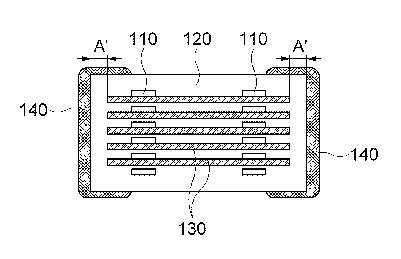
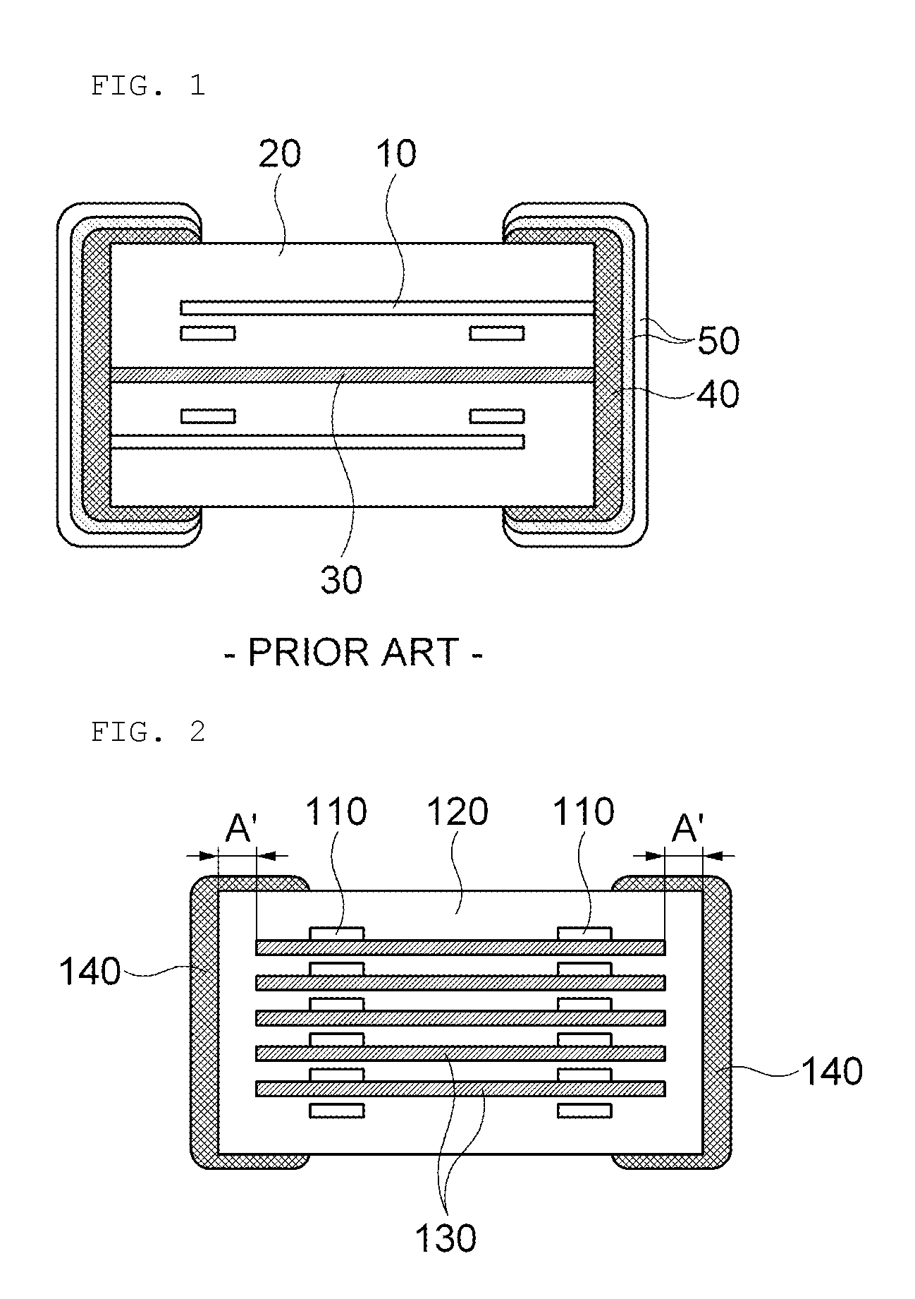
[0068]As shown in FIG. 2, the gap layer was applied to only in the area spaced apart from external electrodes formed at both sides of the body by about 100 μm by using the gap composition. The inner electrode used Ag and the body was formed by adding about 0.2 mol % of one or more additives selected from a group consisting of Bi2O3, CoO, and TiO2 for every 100 mol % of NiZnCu ferrite.

[0069]The multilayered power inductor according to the exemplary embodiment of the present invention has a structure in which three sheets of the gap layer (15 μm) is formed between the bodies.

example 2

[0070]The gap composition in the paste type was prepared by adding 100 g of TiO2 powder (average particle size of 30 nm and specific surface of 40 m2 / g) (30 wt %), 12 g of ethyl cellulose as organic resin (4 wt %), a solvent, that is, 190 g of dihydroterpineol and butyl carbitol (63 wt %), and the rest plasticizer and dispersant. The viscosity of the gap composition was 50 kcps.

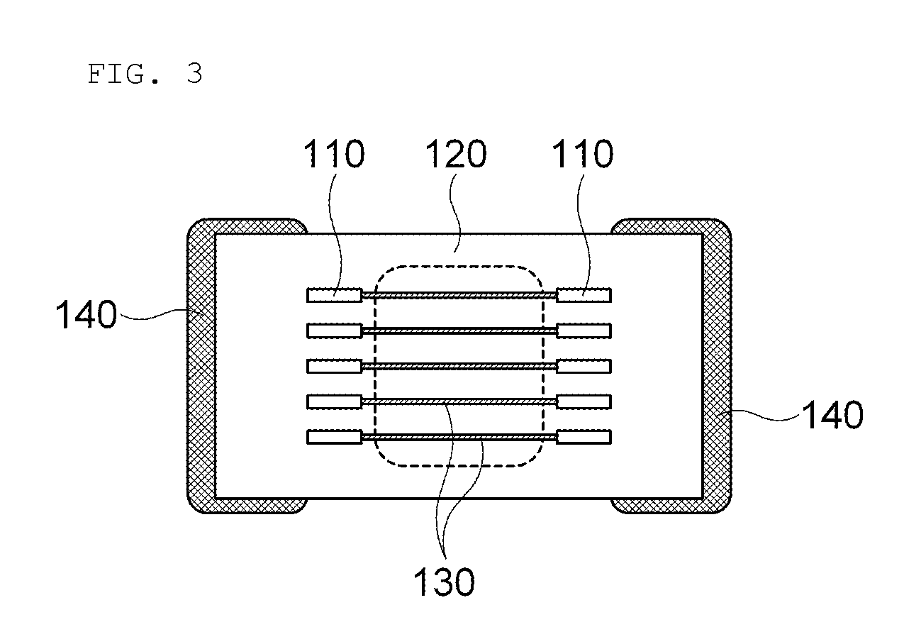
[0071]As shown in FIG. 3, the multilayered power inductor was prepared by the same method as Example 1 except that the gap layer is partially applied only to the core area surrounded by the inner electrode by using the gap composition.

example 3

[0072]The gap composition in the paste type was prepared by adding 100 g of Al2O3 powder (average particle size of 100 nm and specific surface of 10 m2 / g) (45 wt %), 10 g of ethyl cellulose and polyvinyl butyral as organic resin, a solvent, that is, 95 g of dihydroterpinyl acetate, and the rest plasticizer and dispersant. The viscosity of the gap composition was 150 kcps.

[0073]As shown in FIG. 4, the multilayered power inductor was prepared by the same method as Example 1 except that the gap layer is partially applied to the same area in which inner electrodes at both sides are disposed by using the gap composition.


PUM

PropertyMeasurementUnit
specific surface areaaaaaaaaaaa
particle sizeaaaaaaaaaa
temperatureaaaaaaaaaa

Abstract

Disclosed are a multilayered power inductor, including: a body in which a plurality of magnetic layers formed with inner electrodes are stacked; and a plurality of gap layers, wherein the plurality of gap layers are formed so as not to contact external electrodes formed at both sides of the body, and a gap composition of the multilayered power inductor.In addition, as the gap composition, the exemplary embodiment of present invention can prepare tetravalent or tetravalent dielectric oxide into the paste type and applies the gap layer structure thereto, thereby facilitating the structural design and the thickness control of the gap layer as compared with the case of forming the gap layer in the sheet shape of the related art and improving the DC-bias characteristics by maximally suppressing the diffusion with the body.

Description

CROSS REFERENCE(S) TO RELATED APPLICATIONS[0001]This application claims the benefit under 35 U.S.C. Section 119 of Korean Patent Application Serial No. 10-2011-0062945, entitled “Gap Composition Of Multi Layered Power Inductor And Multi Layered Power Inductor Including Gap Layer Using The Same” filed on Jun. 28, 2011, which is hereby incorporated by reference in its entirety into this application.BACKGROUND OF THE INVENTION[0002]1. Technical Field[0003]The present invention relates to a gap composition of a multilayered power inductor and a multilayered power inductor including a gap layer using the same.[0004]2. Description of the Related Art[0005]A multilayered power inductor has been mainly used for a power supply circuit such as a DC-DC converter within portable devices. Meanwhile, the multilayered power inductor has been developed to implement high current, low DC resistance, or the like, while being miniaturized. As a demand for high frequency and miniaturization of the DC-DC ...

Claims


Application Information

Patent Timeline
Patent Type & Authority Patents(United States)
IPC IPC(8): H01F5/00C04B35/26G11B5/708H01F3/14H01F37/00H01F27/28H01F27/29
CPCH01F3/14H01F37/00H01F27/292H01F2027/2809H01F17/00H01F27/00C01G23/04
Inventor SON, SOO HWANAN, SUNG YONGKIM, MYEONG GISONG, SO YEONMOON, BYEONG CHEOL
Owner SAMSUNG ELECTRO MECHANICS CO LTD
Why Eureka
Try Eureka