Extreme ultraviolet lithography system, device, and method for printing low pattern density features

a technology of ultraviolet lithography and features, applied in the field of extreme ultraviolet lithography systems, devices, and methods for printing low pattern density features, can solve the problems of increasing the complexity of ic processing and manufacturing, euv energy is substantially lost on the optical path, and the reflectance of euv masks is very low

Active Publication Date: 2020-06-23
TAIWAN SEMICON MFG CO LTD
View PDF25 Cites 0 Cited by
  • Summary
  • Abstract
  • Description
  • Claims
  • Application Information

AI Technical Summary

Benefits of technology

[0089]Various advantages may present in different embodiments of the present disclosure. In one example, the exposure intensity is enhanced. Accordingly, the exposure duration is reduced and the throughput is increased, especially for the IC pattern with a low pattern density. By utilizing the highly coherent illumination mode and corresponding pupil filtering, the energy loss is substantially reduced. In one example for illustration, the pupil fill ratio (the relative energy loss by the pupil filter) is much less, such as less than about 20%. The exposure light amplitude to the main features is substantially increased and the MEEF is reduced. In another example, the printability of the falling particles is mitigated.

Problems solved by technology

Such scaling down has also increased the complexity of IC processing and manufacturing.
However, the reflectance of EUV mask is very low.
The EUV energy is substantially lost on the optical path.
There are other issues including low throughput issue, especially for a via layer due to the low transmittance through the via.

Method used


Image

  • Extreme ultraviolet lithography system, device, and method for printing low pattern density features
  • Extreme ultraviolet lithography system, device, and method for printing low pattern density features
  • Extreme ultraviolet lithography system, device, and method for printing low pattern density features

Examples


Embodiment Construction

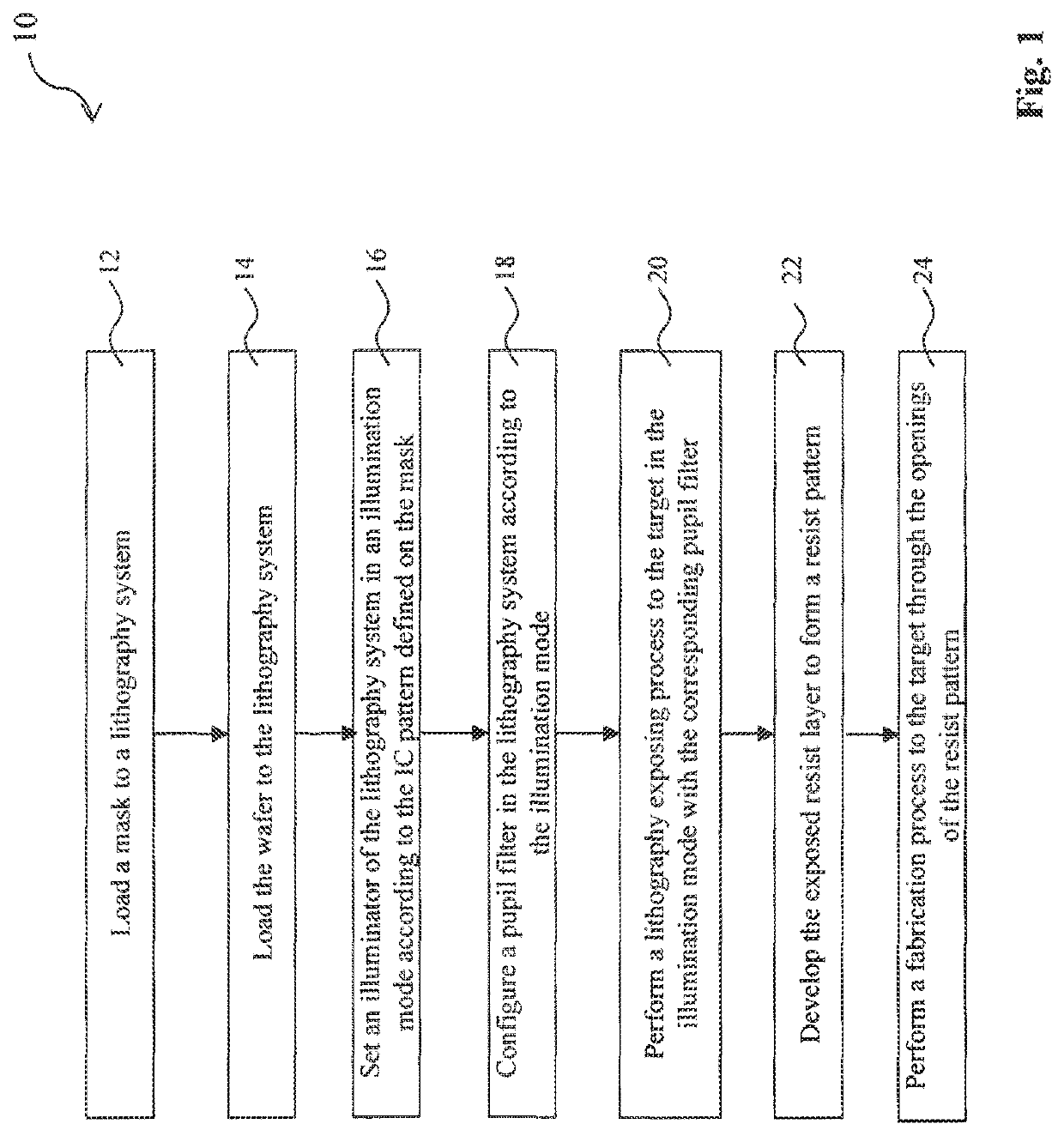
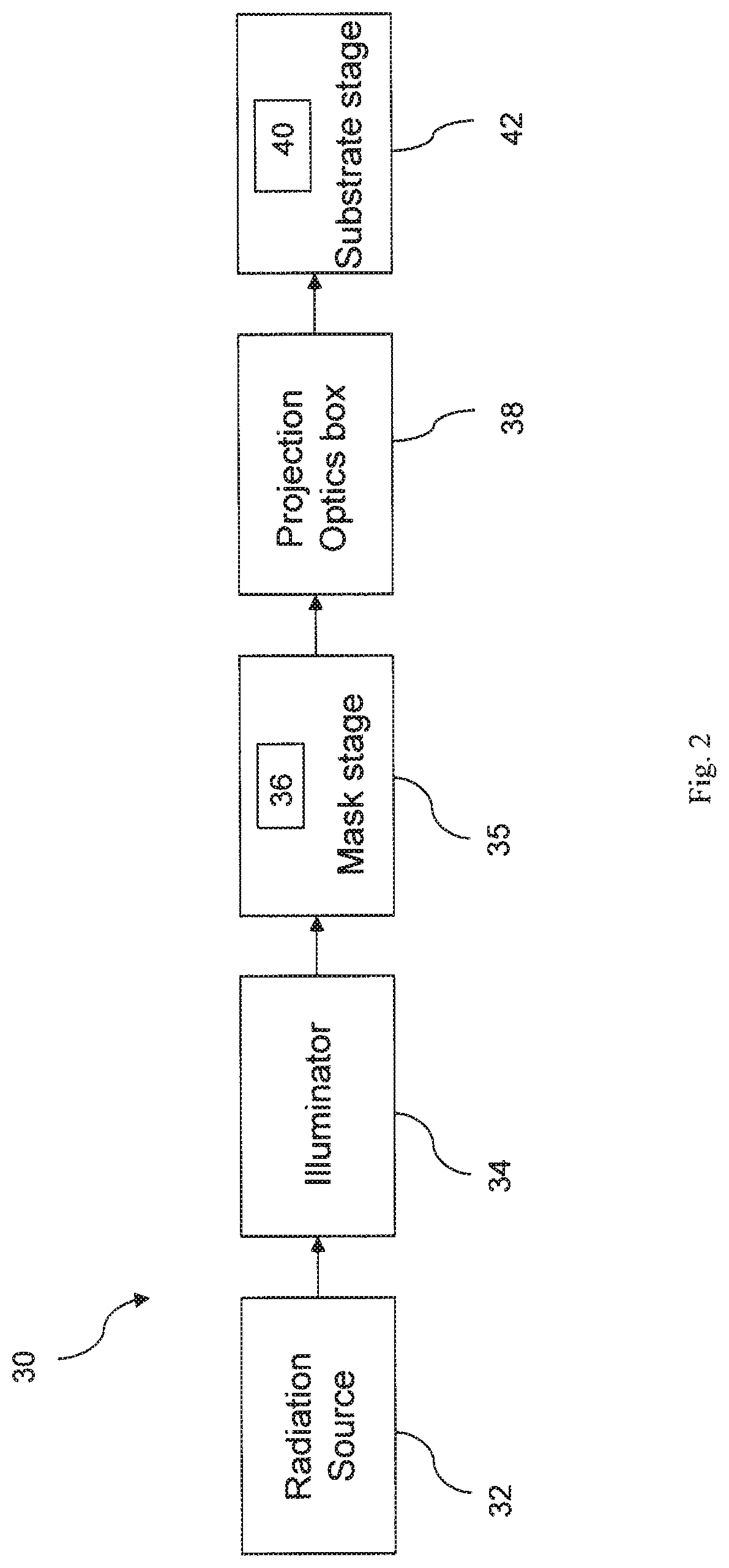
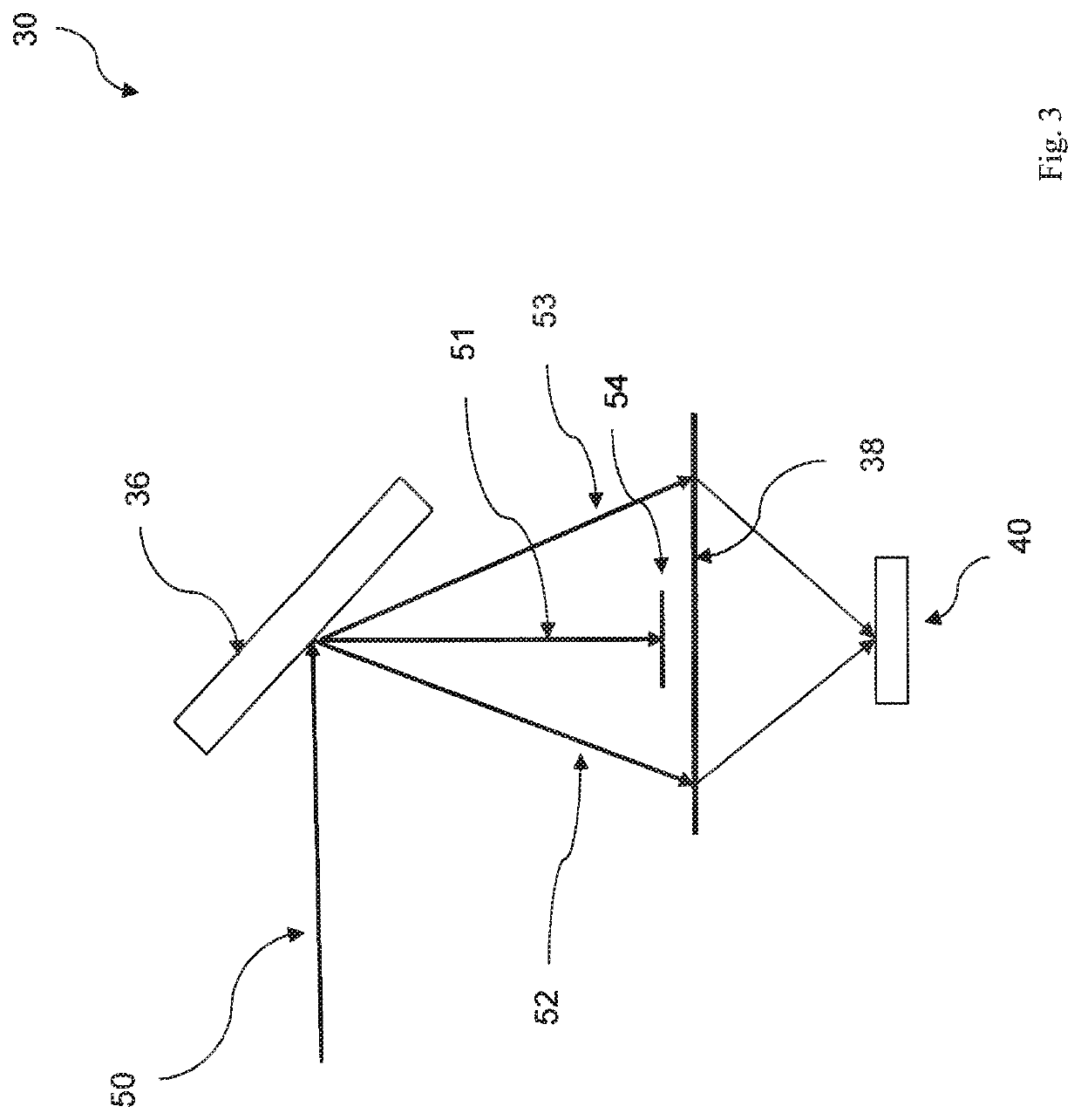
[0034]The following disclosure provides many different embodiments, or examples, for implementing different features. Specific examples of components and arrangements are described below to simplify the present disclosure. These are, of course, merely examples and are not intended to be limiting. For example, the formation of a first feature over or on a second feature in the description that follows may include embodiments in which the first and second features are formed in direct contact, and may also include embodiments in which additional features may be formed between the first and second features, such that the first and second features may not be in direct contact. In addition, the present disclosure may repeat reference numerals and / or letters in the various examples. This repetition is for the purpose of simplicity and clarity and does not in itself dictate a relationship between the various embodiments and / or configurations discussed.

[0035]Further, spatially relative term...


PUM

PropertyMeasurementUnit
thicknessaaaaaaaaaa
thicknessaaaaaaaaaa
thicknessaaaaaaaaaa

Abstract

A lithography system includes a radiation source configured to generate an extreme ultraviolet (EUV) light. The lithography system includes a mask that defines one or more features of an integrated circuit (IC). The lithography system includes an illuminator configured to direct the EUV light onto the mask. The mask diffracts the EUV light into a 0-th order ray and a plurality of higher order rays. The lithography system includes a wafer stage configured to secure a wafer that is to be patterned according to the one or more features defined by the mask. The lithography system includes a pupil phase modulator positioned in a pupil plane that is located between the mask and the wafer stage. The pupil phase modulator is configured to change a phase of the 0-th order ray.

Description

PRIORITY DATA[0001]This application is a continuation application of U.S. patent Ser. No. 15 / 380,717, filed Dec. 15, 2016, now U.S. Pat. No. 10,162,257, issued Dec. 25, 2018, entitled “IMPROVED EXTREME ULTRAVIOLET LITHOGRAPHY SYSTEM, DEVICE, AND METHOD FOR PRINTING LOW PATTERN DENSITY FEATURES,” the entire disclosure of which is incorporated herein by reference.BACKGROUND[0002]The semiconductor integrated circuit (IC) industry has experienced exponential growth. Technological advances in IC materials and design have produced generations of ICs where each generation has smaller and more complex circuits than the previous generation. In the course of IC evolution, functional density (i.e., the number of interconnected devices per chip area) has generally increased while geometry size (i.e., the smallest component (or line) that can be created using a fabrication process) has decreased. This scaling down process generally provides benefits by increasing production efficiency and loweri...

Claims


Application Information

Patent Timeline
Patent Type & Authority Patents(United States)
IPC IPC(8): G03B27/32G03B27/54G03F1/26G03F7/20
CPCG03F7/70308G03F7/70033G03F1/26G03F7/70191G03F7/2004G03F7/70008G03F7/0002G03F7/001G03F7/70716H01L21/0275
Inventor LU, YEN-CHENGYU, SHINN-SHENGCHEN, JENG-HORNGYEN, ANTHONY
Owner TAIWAN SEMICON MFG CO LTD
Why Eureka
Try Eureka