
High efficiency lighting device including one or more solid state light emitters, and method of lighting

a lighting device and solid-state technology, applied in the field of lighting devices, can solve the problems of significant deficiency in green, poor color rendering, and particularity deficient in red color rendering, and achieve the effects of reducing the efficiency of such systems, increasing the complexity and cost of circuitry, and low efficiency

Active Publication Date: 2016-09-13
IDEAL IND LIGHTING LLC
View PDF367 Cites 8 Cited by
  • Summary
  • Abstract
  • Description
  • Claims
  • Application Information

AI Technical Summary

Benefits of technology

[0019]Colored objects illuminated by RGB LED lamps sometimes do not appear in their true colors. For example, an object that reflects only yellow light, and thus that appears to be yellow when illuminated with white light, may appear de-saturated and grayish when illuminated with light having an apparent yellow color, produced by the red and green LEDs of an RGB LED fixture. Such lamps, therefore, are considered not to provide excellent color rendition, particularly when illuminating various settings such as in general illumination and particularly with regard to natural scenes. In addition, currently available green LEDs are relatively inefficient, and thus limit the efficiency of such lamps.
[0020]Employing LEDs having a wide variety of hues would similarly necessitate use of LEDs having a variety of efficiencies, including some with low efficiency, thereby reducing the efficiency of such systems and dramatically increasing the complexity and cost of the circuitry to control the many different types of LEDs and maintain the color balance of the light.
[0021]There is therefore a need for a high efficiency white light source that combines the efficiency and long life of white LED lamps (i.e., which avoids the use of relatively inefficient light sources) with an acceptable color temperature and good color rendering index, a wide gamut and simple control circuitry.

Problems solved by technology

There exist “white” LED lamp light sources which are relatively efficient but which have poor color rendering, typically having CRI Ra values of less than 75, and which are particularity deficient in the rendering of red colors and also to a significant extent deficient in green.
Such lamps, therefore, are considered not to provide excellent color rendition, particularly when illuminating various settings such as in general illumination and particularly with regard to natural scenes.
In addition, currently available green LEDs are relatively inefficient, and thus limit the efficiency of such lamps.
Employing LEDs having a wide variety of hues would similarly necessitate use of LEDs having a variety of efficiencies, including some with low efficiency, thereby reducing the efficiency of such systems and dramatically increasing the complexity and cost of the circuitry to control the many different types of LEDs and maintain the color balance of the light.

Method used


Image

  • High efficiency lighting device including one or more solid state light emitters, and method of lighting
  • High efficiency lighting device including one or more solid state light emitters, and method of lighting
  • High efficiency lighting device including one or more solid state light emitters, and method of lighting

Examples


first embodiment

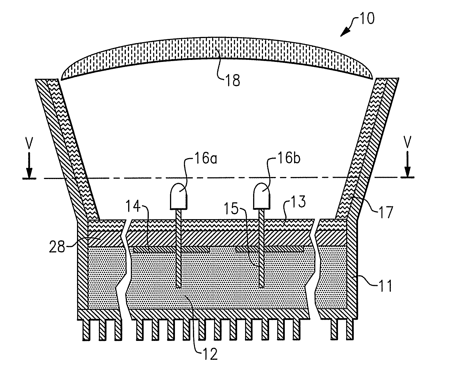
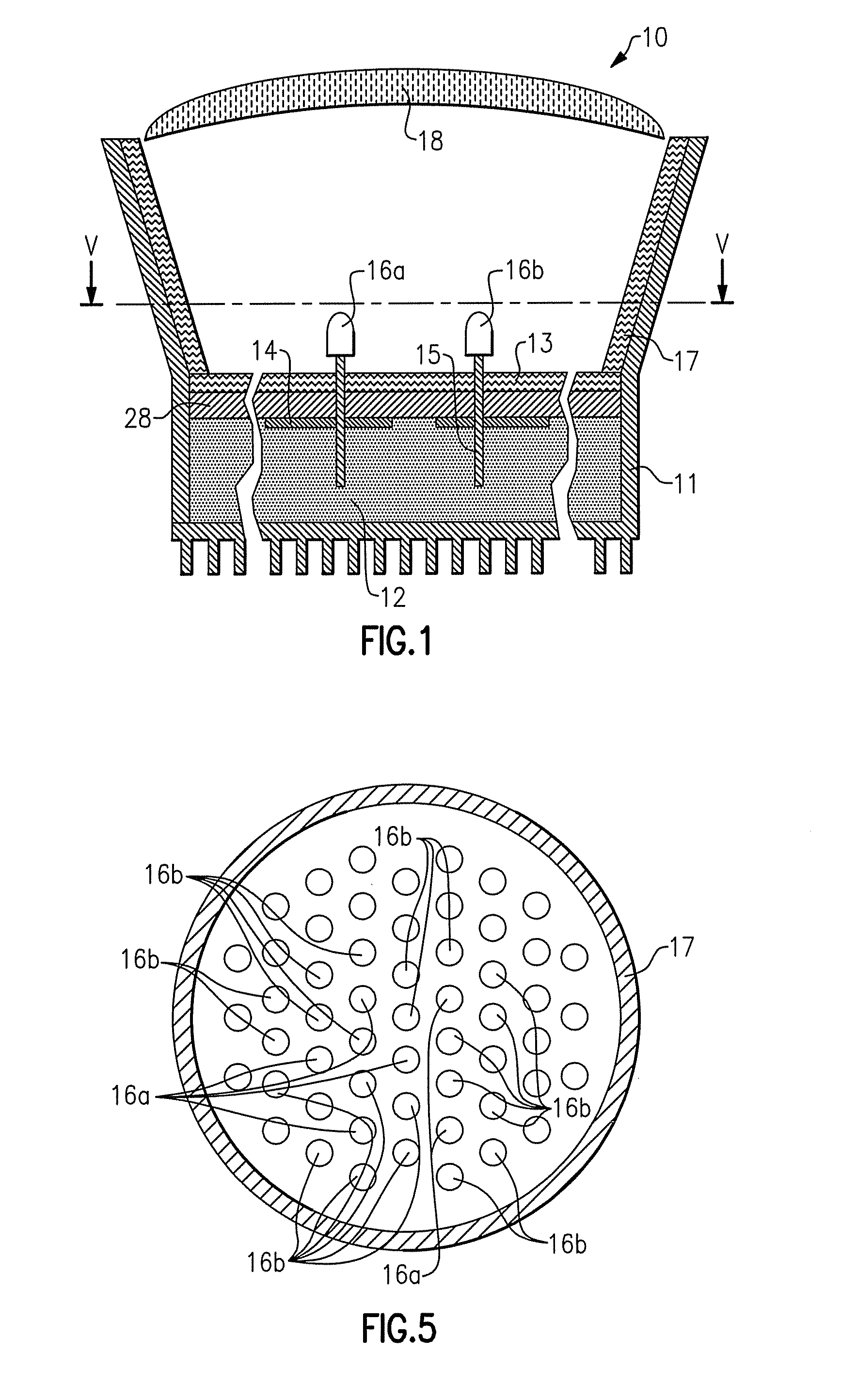
[0410]FIG. 1 depicts a lighting device in accordance with the present inventive subject matter.

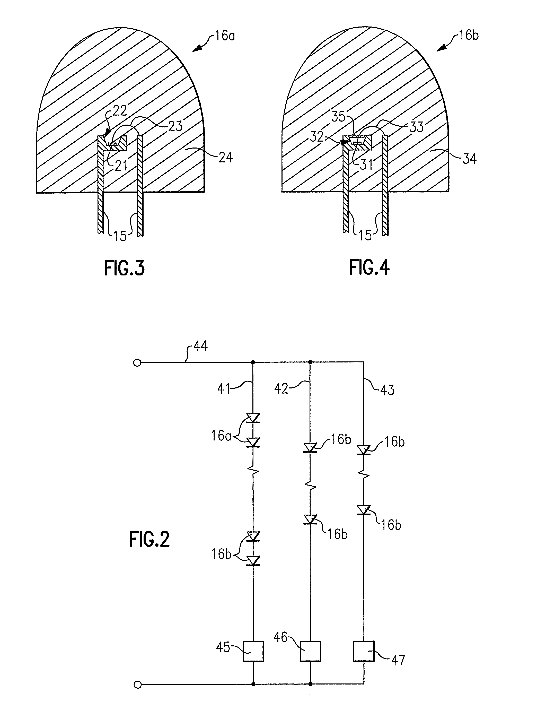
[0411]Referring to FIG. 1, there is shown a lighting device 10 that includes a heat spreading element 11 (formed of aluminum), electrically insulating regions 12 (comprising any desired material which is thermally conductive and not electrically conductive, a wide variety of which are well-known to those skilled in the art, e.g., ceramic, epoxy or silicone optionally filled with silicon carbide, diamond, cubic boron nitride, alumina, etc), a highly reflective surface 13 (which can be formed in situ by polishing the surface of the aluminum heat spreading element, or made of MCPET® (marketed by Furukawa, a Japanese corporation)), conductive traces 14 formed of copper, lead frames 15 formed of silver-plated copper (or silver-plated mild steel), packaged LEDs 16a, 16b (described in more detail below), a reflective cone 17 (made of MCPET®) with a diffuse light scattering surface and a diffusing...

second embodiment

[0439]FIG. 6 depicts a lighting device in accordance with the present inventive subject matter.

[0440]Referring to FIG. 6, there is shown a lighting device 110 which includes a heat spreading element 111 (formed of aluminum), electrically insulating regions 112 (comprising any desired material which is thermally conductive and not electrically conductive, a wide variety of which are well known to those skilled in the art, e.g., ceramic, epoxy or silicone optionally filled with silicon carbide, diamond, cubic boron nitride, alumina, etc), a highly reflective surface 113 (formed in situ by polishing the surface of the aluminum heat spreading element, or made of MCPET® (marketed by Furukawa, a Japanese corporation)), conductive traces 114 formed of copper, lead frames 115 formed of silver-plated copper (or silver-plated mild steel), packaged LEDs 116a, 116b (described in more detail below), a reflective cone 117 (made of MCPET®) with a diffuse light scattering surface and a diffusing el...

third embodiment

[0468]FIG. 11 is a schematic diagram of a high efficiency lamp 150 in accordance with the inventive subject matter. The lamp 150 includes a lower housing 151 and an upper housing 152, light sources 163 and red / orange light emitting diodes 164. The lower housing 151 is a cast aluminum housing having fins surrounding the circumference and provides sidewalls of the mixing enclosure 158. The lower housing may be a lower housing of an LR6 fixture from Cree LED Lighting Solutions, Inc., Durham, N.C., with the trim flange removed such that the housing does not extend past the lens 157. Other suitable lower housing materials having similar thermal properties could also be utilized. The lower housing 151 and the lens 157, in combination, comprise an enclosing structure that surrounds the light sources 163 and the red / orange light emitting diodes 164.

[0469]The upper housing 152 includes a cavity 153 and also has fins to increase the overall area for heat extraction. The upper housing 152 has...


PUM


Abstract

There is provided a lighting device that comprises at least one 600-630 nm solid state light emitter and at least one light source emitting light within an area on a 1931 CIE Chromaticity Diagram defined by a first set of points having x, y coordinates of (0.32, 0.40), (0.36, 0.48), (0.43, 0.45), (0.42, 0.42), (0.36, 0.38), or a second set of points having x, y coordinates of (0.29, 0.36), (0.32, 0.35), (0.41, 0.43), (0.44, 0.49), (0.38, 0.53). Some embodiments further comprise at least a first power line. Also provided are methods that comprise illuminating at least one light source to emit light within one of the areas defined above, and illuminating at least one 600-630 nm emitter.

Description

CROSS-REFERENCE TO RELATED APPLICATIONS[0001]This application claims the benefit of U.S. Provisional Patent Application No. 60 / 868,134, filed Dec. 1, 2006, entitled “Lighting Device and Lighting Method” (inventors: Antony Paul van de Ven and Gerald H. Negley), the entirety of which is hereby incorporated by reference as if set forth in its entirety.[0002]This application is a continuation-in-part of U.S. patent application Ser. No. 11 / 948,021, filed Nov. 30, 2007 (now U.S. Patent Publication No. 2008 / 0130285), the entirety of which is incorporated herein by reference as if set forth in its entirety.[0003]This application is a continuation-in-part of PCT International Patent Application No. PCT / US07 / 86027, filed Nov. 30, 2007 (PCT Publication No. 2008 / 070541), the entirety of which is incorporated herein by reference as if set forth in its entirety.FIELD OF THE INVENTIVE SUBJECT MATTER[0004]The present inventive subject matter relates to a lighting device, in particular, a device tha...

Claims


Application Information

Patent Timeline
Patent Type & Authority Patents(United States)
IPC IPC(8): F21K99/00H05B33/08H05B44/00
CPCF21K9/232H05B33/0803H05B33/0815H05B33/0869H01L2924/181F21Y2101/00H01L2224/45147H01L2224/48091H01L2224/48247F21Y2115/10H05B45/22H05B45/00H01L2924/00012H01L2924/00014H01L2924/00
Inventor VAN DE VEN, ANTONY PAULNEGLEY, GERALD H.
Owner IDEAL IND LIGHTING LLC
Learn More