
Structure for a radio frequency power amplifier module within a radio frequency power amplifier package

a technology of radio frequency power amplifier and structure, which is applied in the direction of rf amplifier, basic electric elements, solid-state devices, etc., can solve the problems of poor predictability of input and output matching impedance and instability of typical packages

Active Publication Date: 2016-07-26
NXP USA INC
View PDF20 Cites 7 Cited by
  • Summary
  • Abstract
  • Description
  • Claims
  • Application Information

AI Technical Summary

Benefits of technology

This patent describes various versions of a radio frequency power amplifier module, package, integrated circuit module, printed circuit board, and base-station. The technical effects of this invention include improved amplification of radio signals, reduced signal loss, reduced power consumption, and improved efficiency. These improvements make it easier to transmit and receive signals over longer distances with higher quality. The patent also describes the use of more advanced techniques such as pneumatic valves, high-speed data transmission, and advanced cooling systems to further enhance the performance of the amplifier.

Problems solved by technology

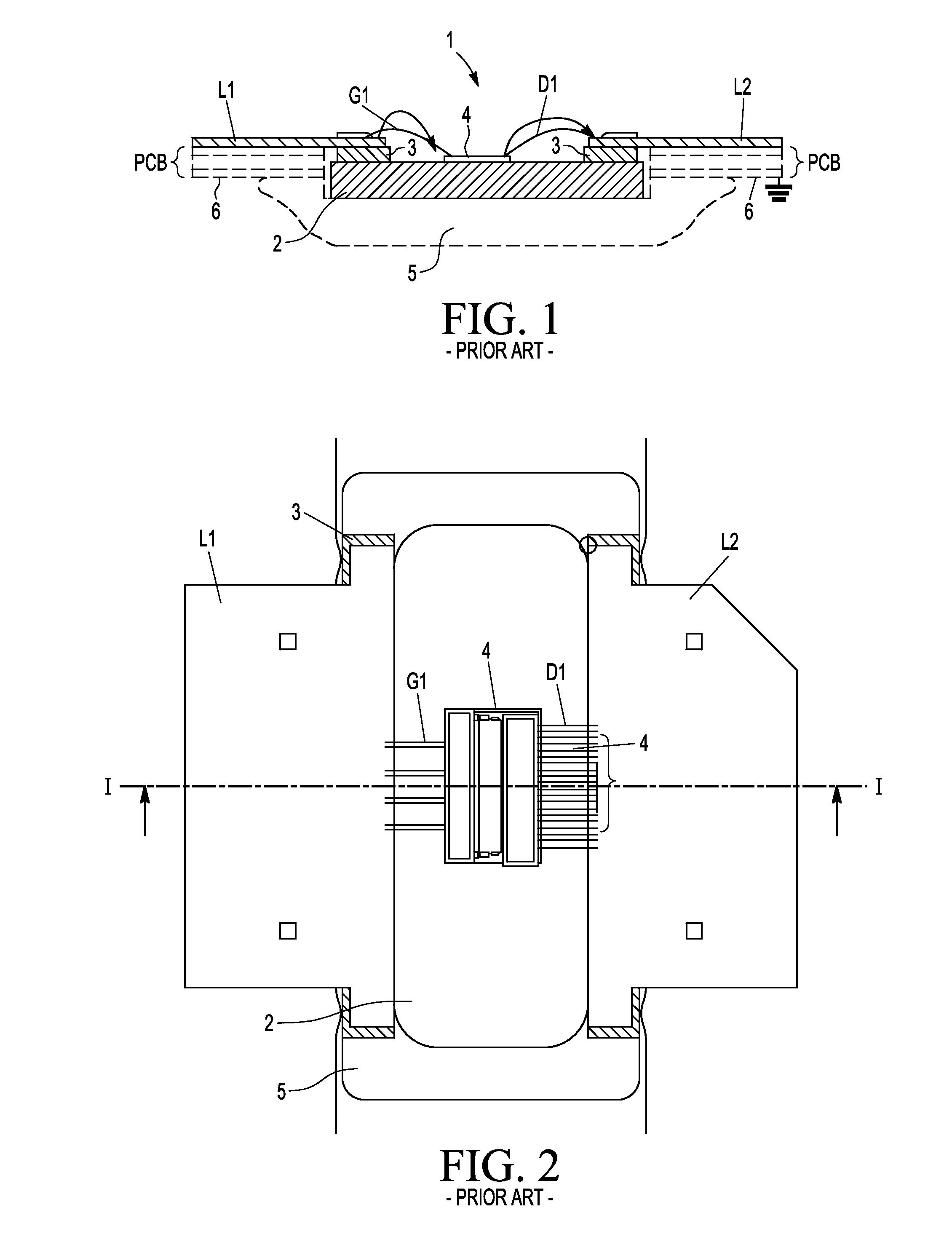
However, this typical package suffers from instability, as well as poor predictability of input and output matching impedances.

Method used


Image

  • Structure for a radio frequency power amplifier module within a radio frequency power amplifier package
  • Structure for a radio frequency power amplifier module within a radio frequency power amplifier package
  • Structure for a radio frequency power amplifier module within a radio frequency power amplifier package

Examples


Embodiment Construction

[0029]Because the illustrated embodiments of the present invention may for the most part, be implemented using electronic components and circuits known to those skilled in the art, details will not be explained in any greater extent than that considered necessary for the understanding and appreciation of the underlying concepts of the present invention and in order not to obfuscate or distract from the teachings of the present invention.

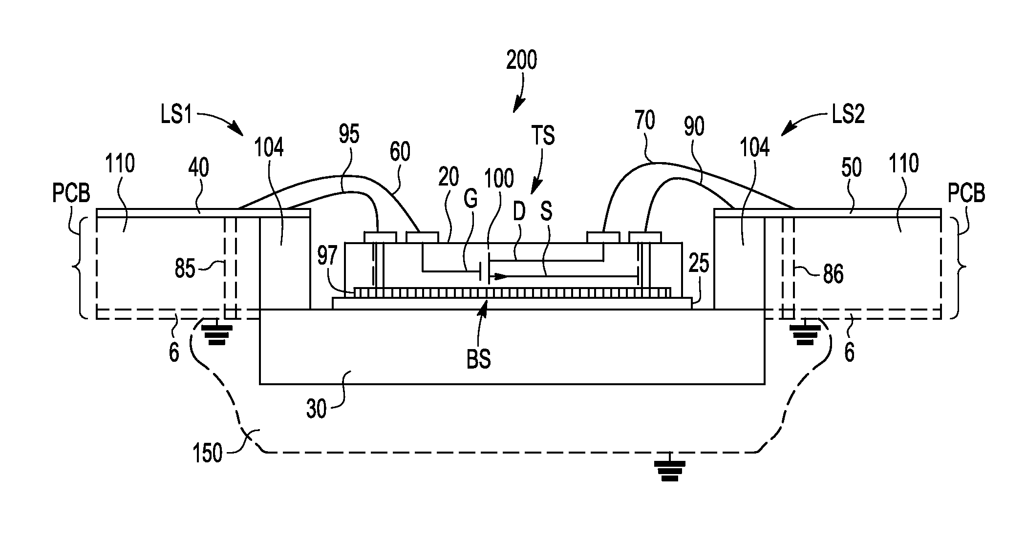
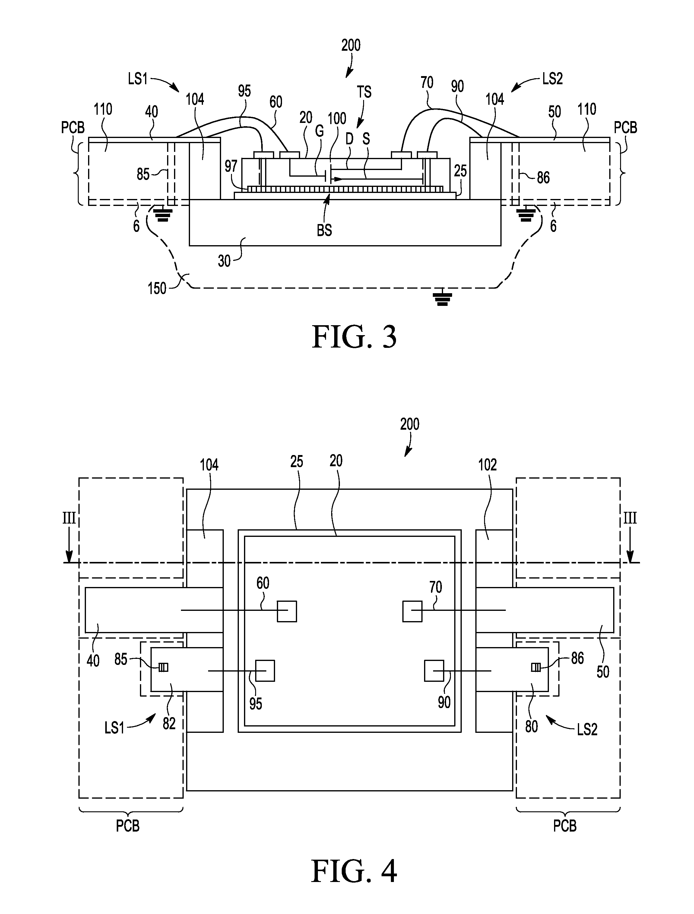
[0030]Referring to FIGS. 3 and 4, the example of a radio frequency power amplifier module 200 is implemented as a radio frequency power amplifier package mountable on a PCB with a flange 30 mountable on a separate heat sink 150. However, alternatively, the RF power amplifier module 200b may be also be provided as a package-less and be mounted directly on a heat sink 151 together with a printed circuit board PCB as shown in the example of FIG. 5.

[0031]The RF power amplifier module 200 comprises an integrated circuit die 20, hereinafter referred to as ...


PUM


Abstract

A RF power amplifier module comprises a die with a RF power transistor and the RF power transistor comprises a control terminal, a transistor output terminal and a transistor reference terminal. The RF power amplifier module further comprises a module input terminal, a module output terminal and at least two module reference terminals being electrically coupled to the control terminal, the transistor output terminal and the transistor reference terminal, respectively. The RF power amplifier module further comprises an electrically isolating layer and a heat conducting element. The die is in thermal contact with the heat conducting element via the electrically isolating layer in order to transfer heat during operation of the RF power transistor to the heat conducting element.

Description

CROSS REFERENCE TO RELATED APPLICATION(S)[0001]The present application claims priority to International Patent Application No. PCT / IB2014 / 000807, entitled “A RADIO FREQUENCY POWER AMPLIFIER MODULE AND A RADIO FREQUENCY POWER AMPLIFIER PACKAGE,” filed on Apr. 17, 2014, the entirety of which is herein incorporated by reference.FIELD OF THE INVENTION[0002]This invention relates to a radio frequency power amplifier module and a radio frequency power amplifier package. The invention further relates to a radio frequency power amplifier integrated circuit module, to a printed circuit board and to a base station used in mobile communications systems.BACKGROUND OF THE INVENTION[0003]Radio frequency power amplifiers are devices typically comprising a large RF power amplifier transistor that amplifies a RF signal and transfers the RF signal to a load termination through an impedance matching circuit. RF power amplifier transistors are typically integrated in an active die which is typically ar...

Claims


Application Information

Patent Timeline
Patent Type & Authority Patents(United States)
IPC IPC(8): H01L23/10H03F3/195H01L23/66H03F1/08H03F1/30H03F3/24H03F3/213
CPCH03F3/195H01L23/66H03F1/086H03F1/301H03F3/213H03F3/245H01L2224/48091H01L2224/48227H01L2224/49175H01L2224/73265H01L2924/19107H03F2200/447H03F2200/451H01L2924/00014H01L2224/05554H01L23/367H01L24/29H01L24/32H01L24/48H01L24/49H01L24/73H01L2223/6611H01L2223/6616H01L2223/6655H01L2224/04026H01L2224/04042H01L2224/06181H01L2224/2919H01L2224/2929H01L2224/29339H01L2224/32245H01L2224/48235H01L2224/49052H01L2924/10272H01L2924/10329H01L2924/1033H01L2924/1421H01L2924/15151H01L2924/3011H01L2224/45099
Inventor BLEDNOV, IGOR IVANOVICHJONES, JEFFREY K.VOLOKHINE, YOURI
Owner NXP USA INC
Learn More