
Conducting polymer-transition metal electro-catalyst compositions for fuel cells

a technology of electrocatalyst and polymer, which is applied in the direction of non-metal conductors, cell components, conductors, etc., can solve the problems of fuel cell failure, possible fire hazards, and insufficient utilization of electrocatalyst sites, so as to improve catalyst utilization efficiency, improve fuel cell performance, and reduce ohmic loss

Active Publication Date: 2016-04-19
NANOTEK INSTR GRP LLC
View PDF27 Cites 0 Cited by
  • Summary
  • Abstract
  • Description
  • Claims
  • Application Information

AI Technical Summary

Benefits of technology

This approach significantly reduces Ohmic loss, enhances catalyst utilization efficiency, and increases fuel cell output voltage by establishing interconnected paths for electrons, protons, and reactants, improving overall performance.

Problems solved by technology

While the slurry preferably wets the substrate surface to some extent, it must not penetrate too deeply into the substrate, otherwise some of the catalyst will not be located at the desired membrane-electrode interface.
Electro-catalyst sites are not productively utilized if the protons do not have a means for being quickly transported to the ion-conducting electrolyte.
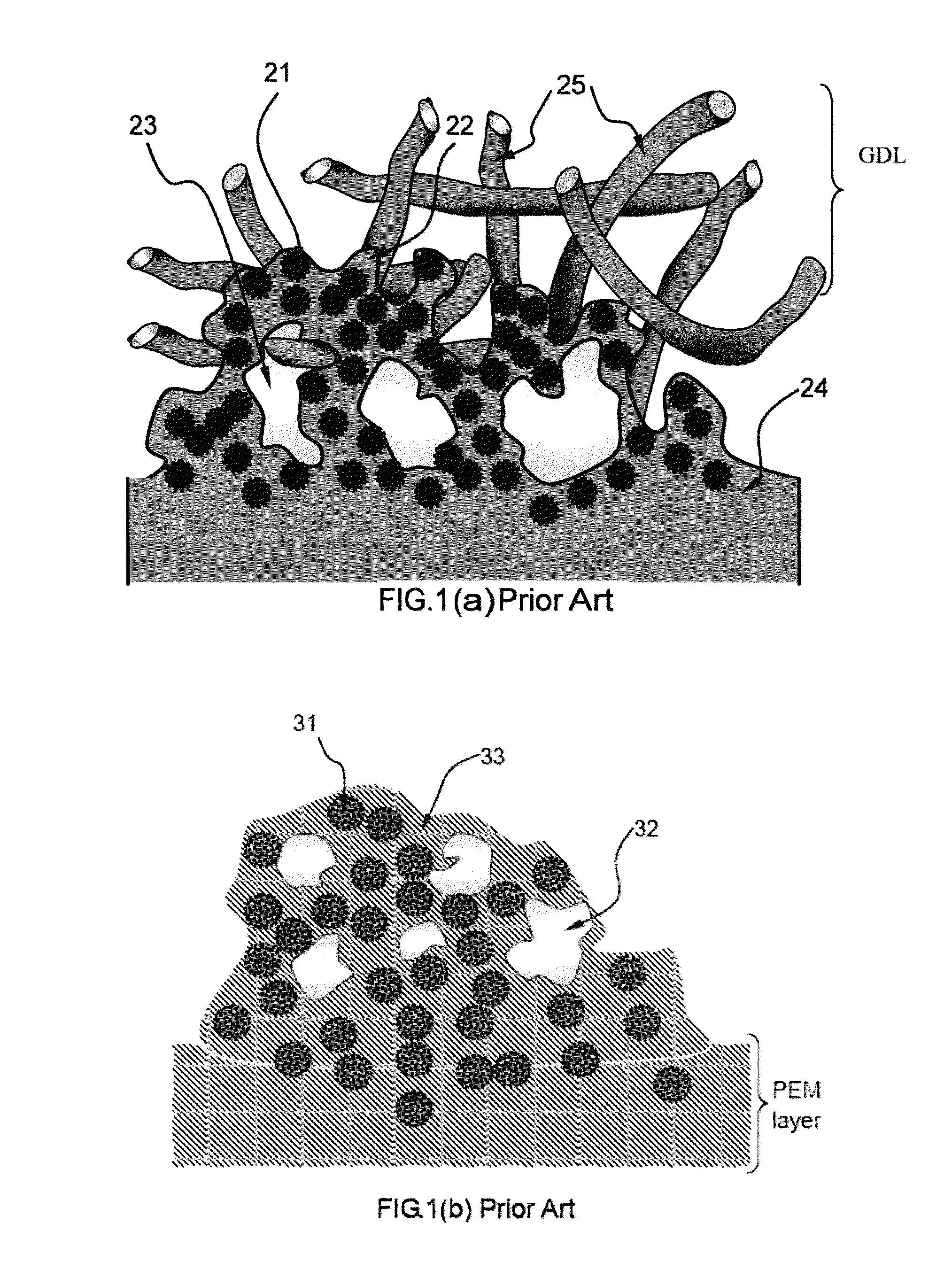
However, this prior-art approach [1-9] of ionomer impregnation into the electrode layer and / or onto electro-catalyst particle surfaces has a serious drawback in that the ionomer commonly used as the PEM material, although ion-conducting (proton-conducting), is not electronically conducting (FIG. 1(a).
This is due to the consideration that a proton-exchange membrane, when serving as the solid electrolyte layer, cannot be an electronic conductor; otherwise, there would be internal short-circuiting, resulting in fuel cell failure and possible fire hazard.
This would prevent the electrons generated at the catalyst sites from being quickly collected by the anode electrode substrate layer and the current collector, thereby significantly increasing the Ohmic resistance and reducing the fuel cell performance.
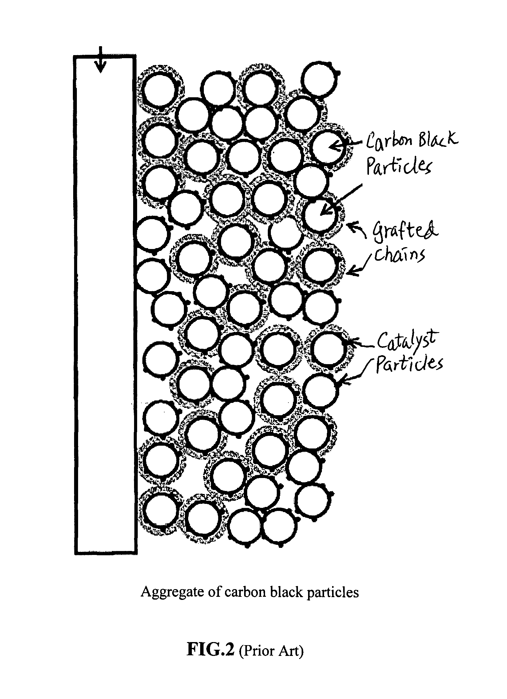
(1) Srinivas's compositions are basically carbon black (CB) particles with their surfaces chemically bonded with either SO3H type functional groups or a mono-layer of conductive polymer chains. In essence, these are just surface-modified CB particles that contain a minute amount of surface functional groups and chains. In the resulting electrode, individual CB particles were being packed together but remaining as discrete particles (FIG. 1 of Ref. 12-14) in such a manner that the surface-bound chains were of insufficient amount to form a continuous matrix material of structural integrity. The requirement for these particles to strictly maintain a contiguous network is a major drawback of this prior art technology.
First, it is not natural for discrete particles to form and maintain contiguity, unless the volume fraction of these particles is excessively high with respect to the surface-bound groups or chains. In such a high-loading situation (with only a small amount of surface bound groups or chains), the resulting cluster or aggregate structure is very weak in terms of mechanical strength and, hence, tends to form cracks and fail to perform its intended functions.
(3) Srinivas's compositions involved complicated and time-consuming surface chemical bonding, grafting, and / or polymerization procedures.
Such a surface-treated CB still has limited conductivity improvements.
In fact, Srinivas could not even measure the electron and proton conductivity of these mono-layers of surface groups or grafted polymer chains.
This is not always possible when they are used to form an electrode bonded to a PEM surface or a carbon paper surface.
Due to only an extremely thin layer of chemical groups or chains being bonded to an individual CB particle, the resulting electrode can be very fragile and interconnected pores (desirable for gas diffusion) tend to interrupt their contiguity.
Operationally, it is very difficult to form an integral layer of catalytic electrode from these modified CB particles alone.
This is not always possible when they are used to form an electrode bonded to a PEM surface or a carbon paper surface.
The resulting electrode can be very fragile and subject to quick failure caused by impact, vibration, or thermal cycling when a fuel cell is in use.
[26], these composite particle-based catalysts tend to exhibit “inferior performance” presumably due, in part, to the Pt particles being too large (typically just under 1 μm).
[Ref. 28] observed some limited improvements over conventional Nafion-supported catalyst electrode.
Presumably, these electrode structures do not provide the required bi-networks of charge transport paths.
They could also limit the transport of fuels (particularly when larger-than-hydrogen molecules such as alcohol are involved) at the anode and interfere with the removal of water from the cathode.

Method used


Image

  • Conducting polymer-transition metal electro-catalyst compositions for fuel cells
  • Conducting polymer-transition metal electro-catalyst compositions for fuel cells
  • Conducting polymer-transition metal electro-catalyst compositions for fuel cells

Examples


example 1

Synthesis, Complexing and Reduction of Sulfonated Polyaniline (S-PANi)

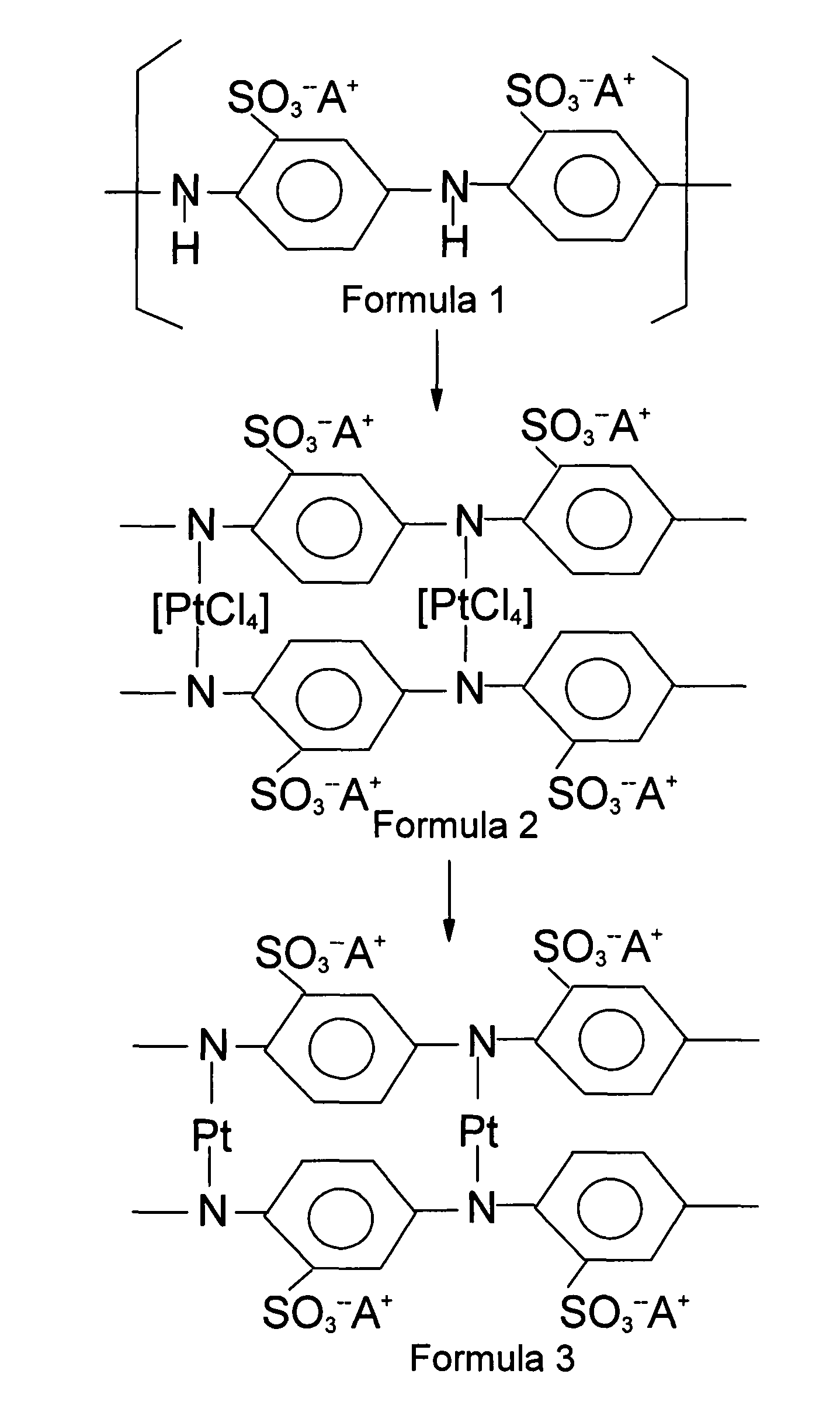
[0095]The chemical synthesis of the S-PANi polymers was accomplished by reacting polyaniline with concentrated sulfuric acid. The procedure was similar to that used by Epstein, et al. (U.S. Pat. No. 5,109,070, Apr. 28, 1992). The resulting S-PANi can be represented by Formula 4 with R1, R2, R3, and R4 group being H, SO3− or SO3H with the content of the latter two being varied between 30% and 75% (i.e., the degree of sulfonation varied between 30% and 75%). The proton conductivity of these SO3− or SO3H-based S-PANI compositions was in the range of 3×10⁻³ S / cm to 4×10⁻² S / cm and their electron conductivity in the range of 0.1 S / cm to 0.5 S / cm when the degree of sulfonation was from approximately 30% to 75% (with y being approximately 0.4-0.6).

[0096]Subsequently, 6.78 g of sulfonated polyaniline (with R1═SO3−, and R2═R3, ═R4═H in Formula 1) and 100 ml of distilled water were mixed in an Erlenmeyer flask for 30 minute...

example 2

[0099]As in example 1, 5.73 g of sulfonated polyaniline were suspended in 100 ml of distilled water. Then, 80 ml of 1.15% aqueous H2IrCl6 were added slowly to the polyaniline suspension / solution for a period of 60 minutes while stirring constantly. The resulting sulfonated polyaniline-IrCl4 complex was separated by centrifuging and decanting. The resulting solid was rinsed with distilled water until the rinse water had a pH value of 7.

[0100]The reductant solution of Example 1 was added to the sulfonated polyaniline-IrCl4 complex for a period of 2 hours at a temperature of 60° C. The product of this reaction was rinsed with distilled water until the rinse water had a pH of 7, and then was dried at 110° C. for 24 hours.

example 3

[0101]As in example 1, 5.73 g of sulfonated polyaniline were suspended (and partially dissolved) in 100 ml of distilled water. Then, 100 ml of 3.15% aqueous Ni(ClO4)2-6H2O were added slowly to the polyaniline suspension / solution for a period of 60 minutes while stirring constantly to produce sulfonated polyaniline-NiCl2 complex. The reductant solution of Example 1 was added to the sulfonated polyaniline-NiCl2 complex for a period of 2 hours at a temperature of 60° C. to produce the desired heterogeneous catalyst polymer containing Ni atoms covalently bonded thereto and presumably additional Ni nano particles physically dispersed in the polymer matrix. TEM studies indicate that a majority of the nano catalyst particles are smaller than 1.5 nm in size with a sizable number of them are approximately 0.5-0.6 nm.


PUM

PropertyMeasurementUnit
proton conductivityaaaaaaaaaa
ion conductivityaaaaaaaaaa

Abstract

An electro-catalyst composition for use as an electrode, gas diffusion layer-supported electrode, catalytic electrode-coated solid electrolyte layer, and / or membrane-electrode assembly in a proton exchange membrane (PEM) type fuel cell. The composition comprises: (a) a proton- and electron-conducting polymer having at least one heteroatom per backbone monomer unit thereof and a plurality of neutral transition metal atoms covalently bonded to at least a portion of the heteroatoms; wherein the polymer has an electronic conductivity no less than 10−4 S / cm and a proton conductivity no less than 10−5 S / cm. Preferably, the electro-catalyst composition further comprises (b) a plurality of catalytically active particles of a transition metal, nucleated around the covalently bonded transition metal atoms. Also preferably, additional catalytically active catalyst particles with an average dimension smaller than 2 nm (most preferably smaller than 1 nm) are physically dispersed in such a polymer and typically not chemically bonded thereto. A hydrogen-oxygen PEM fuel cell or a direct methanol fuel cell (DMFC) featuring such an electro-catalyst composition in a thin-film electrode exhibits a superior current-voltage response.

Description

FIELD OF THE INVENTION[0001]This invention relates to an electro-catalyst composition that can be used in a fuel cell electrode, a catalyst-coated membrane (CCM), and a membrane-electrode assembly (MEA). The composition forms a thin electrode layer that is both proton- and electron-conductive, which is particularly useful for proton exchange membrane-type fuel cells (PEM-FC), including hydrogen-fed and direct alcohol fuel cells.BACKGROUND OF THE INVENTION[0002]The proton exchange membrane or polymer electrolyte membrane fuel cell (PEM-FC) has been a topic of highly active R&D efforts during the past two decades. The operation of a fuel cell normally requires the presence of an electrolyte and two electrodes, each comprising a certain amount of catalysts, hereinafter referred to as electro-catalysts. A hydrogen-oxygen PEM-FC uses hydrogen or hydrogen-rich reformed gases as the fuel while a direct-methanol fuel cell (DMFC) uses methanol solution as the fuel. The PEM-FC and DMFC, or ot...

Claims


Application Information

Patent Timeline
Patent Type & Authority Patents(United States)
IPC IPC(8): H01M4/90H01M8/10H01B1/12H01M4/92H01M4/86
CPCH01M8/1004H01B1/122H01M4/8605H01M4/8652H01M4/9008H01M4/921H01M2008/1095Y02E60/521Y02E60/50
Inventor JANG, BOR Z.ZHAMU, ARUNA
Owner NANOTEK INSTR GRP LLC
Learn More