
One-dimensional global rainbow measurement device and measurement method

a global rainbow and measurement device technology, applied in the direction of optical radiation measurement, instruments, spectrometry/spectrophotometry/monochromators, etc., can solve the problems of limited application and limited global rainbow technique to single-point measuremen

Active Publication Date: 2015-12-22
ZHEJIANG UNIV
View PDF2 Cites 19 Cited by
  • Summary
  • Abstract
  • Description
  • Claims
  • Application Information

AI Technical Summary

Benefits of technology

Enables real-time, non-contact measurement of size, refractive index, and temperature distribution of spray droplets in a one-dimensional line, overcoming the single-point measurement limitation and facilitating the analysis of complex spray fields, with potential for industrial online applications and monitoring of dynamic changes in spray fields.

Problems solved by technology

The methods as mentioned above may damage the original flow field, resulting in errors and great limitations in application, and are thus not applicable to the present measurement requirements.
So far, the global rainbow technique is restricted to single-point measurement.

Method used


Image

  • One-dimensional global rainbow measurement device and measurement method
  • One-dimensional global rainbow measurement device and measurement method
  • One-dimensional global rainbow measurement device and measurement method

Examples


embodiment 1

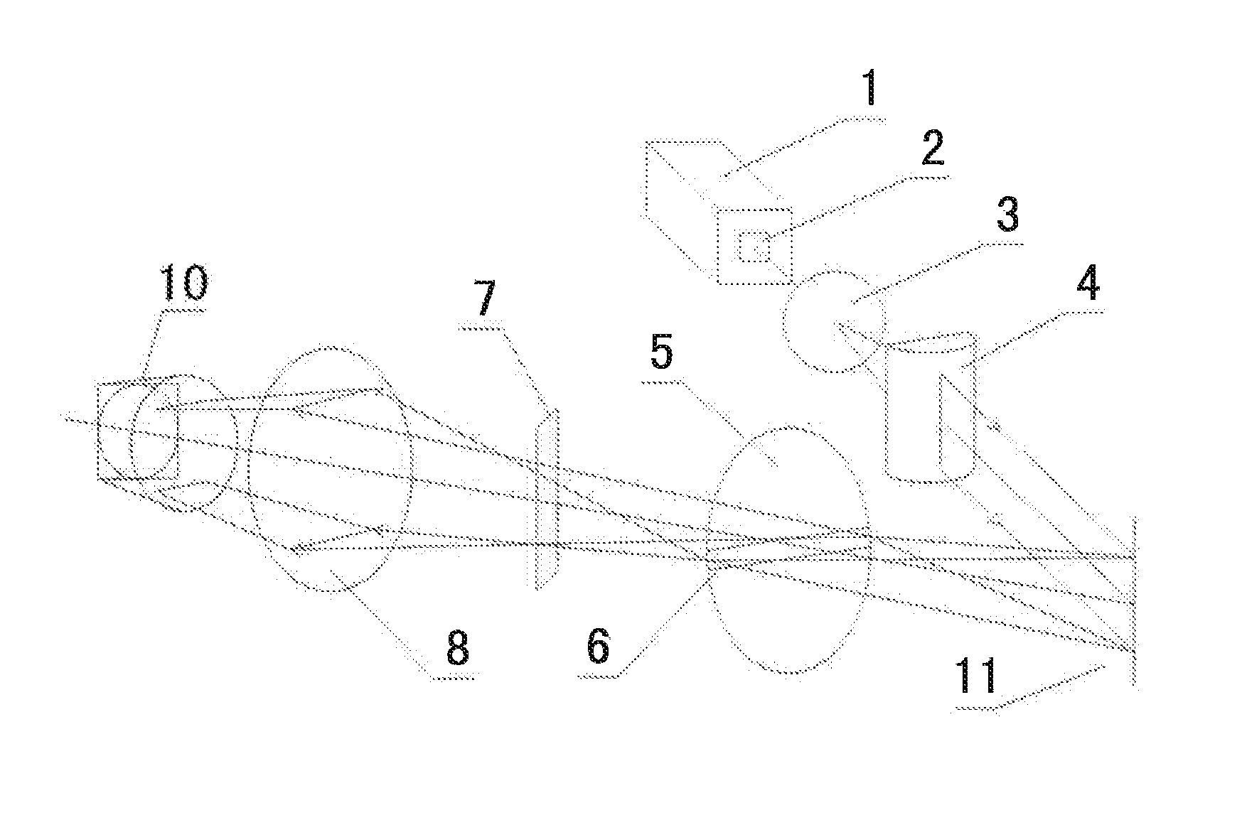
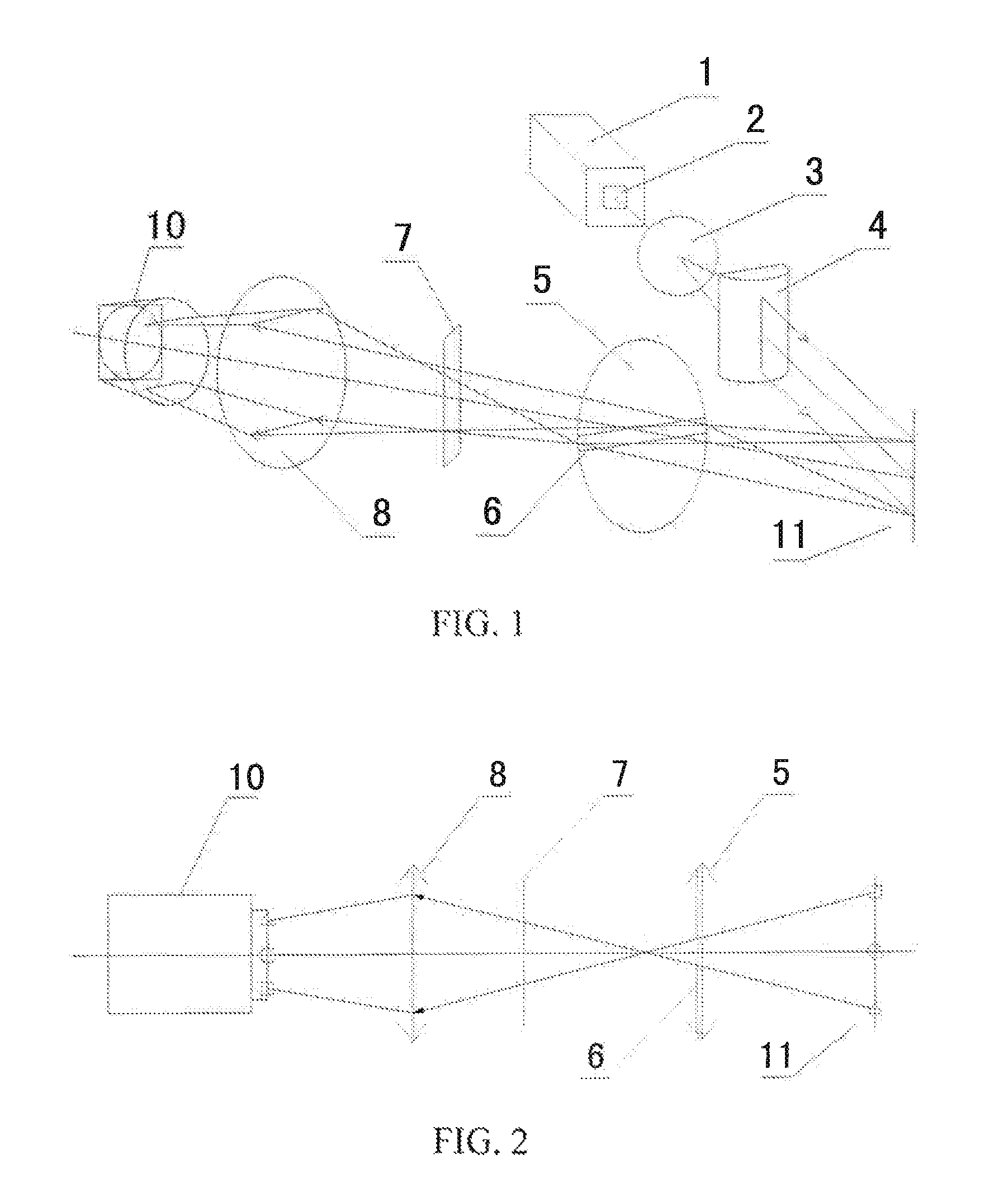
[0043]In Embodiment 1 as shown in FIG. 1 and FIG. 2, a one-dimensional global rainbow measurement device is provided, comprising three parts, i.e., a laser emission unit, a signal collection unit and a signal processing unit.

[0044]a. The laser emission unit is modulated to be a light sheet by a laser beam emitted by a laser, and configured to irradiate droplets in a spray field to generate rainbow signals. The laser emission unit consists of the following three parts:

[0045]a semiconductor laser 1, configured to generate an intensity adjustable laser beam, the semiconductor laser in this embodiment being a 40 mW-600 mW intensity adjustable laser fixed on a rotary stage of which the repeat positioning accuracy is less than 0.005 and the resolution is 0.00125°;

[0046]a modulator element, configured to modulate the emergent laser beam into a polarized light sheet, the modulator element comprising a polarizer 2, a beam expander 3 and a cylindrical lens 4; and

[0047]a bench system, configur...

embodiment 2

[0060]A filter 9 (referring to FIG. 3 and FIG. 4) is provided in front of the CCD signal collector in Embodiment 2, the semiconductor laser is a 50 mW intensity adjustable laser, and the remaining is the same as that in Embodiment 1.

[0061]In this embodiment, the power of the semiconductor laser may be within 40 mW-600 mW. The line width of the horizontal diaphragm on the front side of the field lens may be within 0.5 mm-5 mm. The diameter of both the field lens and the imaging lens may be within 80 mm-120 mm, and the focal length of the both two may be within 100 mm-250 mm,


PUM

PropertyMeasurementUnit
aperture widthaaaaaaaaaa
frequencyaaaaaaaaaa
heightaaaaaaaaaa

Abstract

The present invention provides a one-dimensional global rainbow measurement device and a measurement method. The measurement device comprises three parts, i.e., a laser emission unit, a signal collection unit and a signal processing unit. The laser emission unit is modulated to be a light sheet by a laser beam emitted by a laser, and configured to irradiate droplets in a spray field to generate rainbow signals. The signal collection unit is configured to separately image, by an optical system unit, the rainbow signals at measurement points of different height onto different row pixels of a CCD signal collector. The signal processing unit is configured to convert the received rainbow signals and process by a computer the rainbow signals in a form of data to obtain the measured values. The present invention can analyze gas-liquid phase flow fields during the injection, realize the online measurement of fuel atomization, spray and other processes, and can measure the refractive index, size, temperature and other parameters of the spray droplets in a real-time and non-contact manner.

Description

TECHNICAL FIELD[0001]The present invention relates to the field of gas-liquid two-phase flow measurement, particularly to global rainbow measurement device and method for measuring the size, refractive index, temperature and other parameters of spray droplets in a one-dimensional manner.BACKGROUND OF THE INVENTION[0002]Spray is a common gas-liquid two-phase flow phenomenon in the filed of energy environment at present, for example, atomization, evaporation and combustion of liquid fuel, gas-liquid mixture and absorption in a desulfurization and denitrification rainmaker, etc. In the art, there have been various techniques for measuring a spray field. Conventional contact measurement methods include: immersion, tracking, sedimentation, freezing, wax melting, instant sampling, etc. The methods as mentioned above may damage the original flow field, resulting in errors and great limitations in application, and are thus not applicable to the present measurement requirements. However, man...

Claims


Application Information

Patent Timeline
Patent Type & Authority Patents(United States)
IPC IPC(8): G01J3/46G01N15/02G01J3/14G01J3/28G01N15/00
CPCG01J3/14G01J3/2823G01N15/0211G01J3/46G01N2015/0277G01N2015/0046G01J3/04G01J3/2803G01N21/4788G01N21/53
Inventor WU, XUECHENGCEN, KEFAWANG, ZHIHUAGAO, XIANGCHEN, LINHONGQIU, KUNZANWU, YINGCHUNJIANG, HAOYU
Owner ZHEJIANG UNIV
Learn More