
Efficient combined advanced treatment method of electroplating waste water

a wastewater and advanced treatment technology, applied in water/sewage multi-stage treatment, water/sewage treatment by ion exchange, sustainable biological treatment, etc., can solve the problems of heavy pollution, complex composition of wastewater therefrom, and inability to meet discharge standards, etc., to achieve low treatment cost, high compatibility with wastewater, and good economic performan

Active Publication Date: 2015-10-15
NANJING UNIV +1
View PDF3 Cites 30 Cited by
  • Summary
  • Abstract
  • Description
  • Claims
  • Application Information

AI Technical Summary

Benefits of technology

The present invention provides an efficient combined advanced treatment method for electroplating wastewater. The method uses a combination of processes, including bio-contact oxidation, coagulation, magnetic resin adsorption, and fixed bed resin adsorption. The method ensures that the chemical oxygen demand CODcr is 20 mg / L or below, and removes heavy metals, such as copper and nickel, to very low levels. The method is compatible with wastewater, economical, and has a low treatment cost.

Problems solved by technology

Electroplating industry causes heavy pollution, and the composition of the wastewater therefrom is complex due to the numerous electroplating types and the troublesome process.
However, with the implementation of the new Discharge Standard for Pollutants from Electroplating (GB21900-2008), the discharge standard cannot be met if the electroplating wastewater is treated following the existing conventional treatment methods.
However, the activated carbon is difficult to be regenerated, and is costly in industrialization.
Electroplating wastewater is characterized by high salinity and poor biodegradability.
It is still a difficulty in research to develop an economical and efficient combined advanced treatment technique for electroplating wastewater.

Method used


Image

  • Efficient combined advanced treatment method of electroplating waste water
  • Efficient combined advanced treatment method of electroplating waste water

Examples


example 1

[0026]In this example, electroplating wastewater of a workshop after pretreatments including cyanide breaking, dechromisation and coagulating sedimentation, was treated. The water quality of the effluent after pretreatments is shown in Table 1. The treatment steps were as follows.

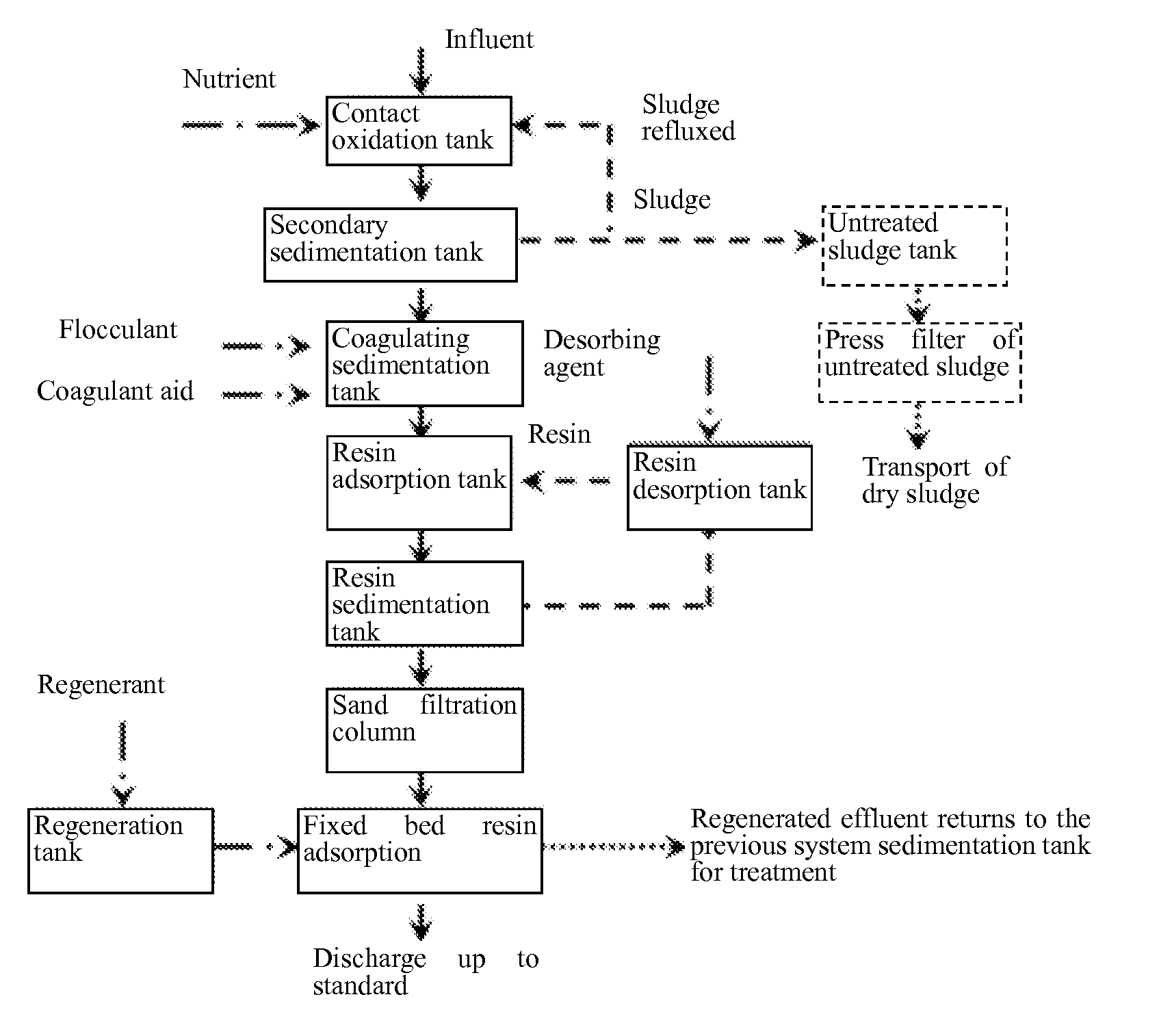
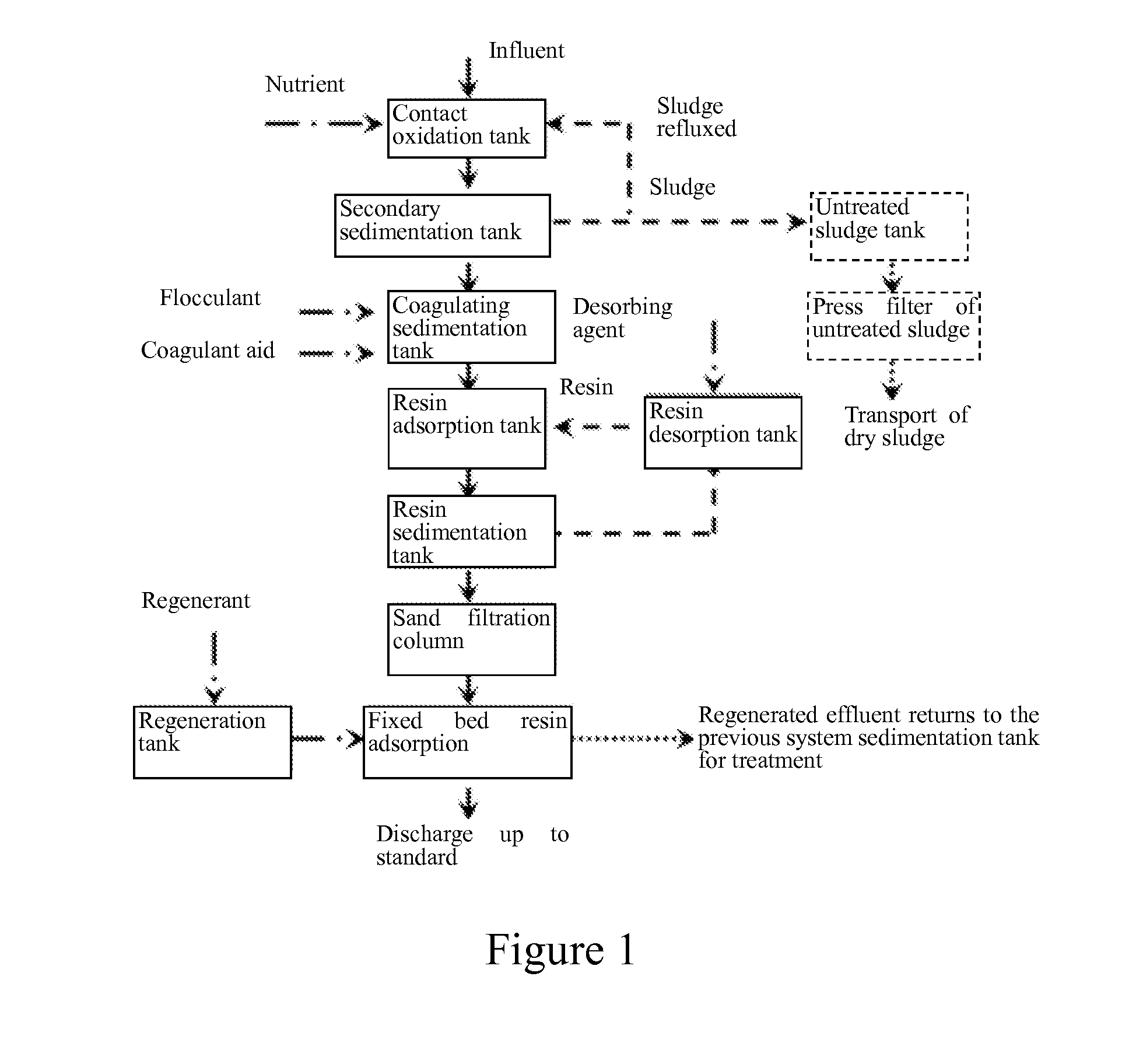
[0027](1) Bio-contact oxidation: An influent at a pH of 7.0 and at a temperature of 15° C. was introduced to a 100 L bio-contact oxidation tank at a rate of 10 L / h. Glucose was added to adjust the BOD / COD to 0.3. The dissolved oxygen (DO) was maintained at 3.5 mg / L by intermittent aeration with an aerator, and the hydraulic retention time was 10 h. The sludge generated in the contact oxidation tank was filter-pressed by a plate and frame filter press, and then the dry sludge was transported for treatment.

[0028](2) Coagulating sedimentation: The effluent from the step (1) was charged to a coagulating sedimentation tank. A polyferric flocculant polyferric sulfate (PFS) was used in an amount 1% by volume of th...

example 2

[0031]In this example, electroplating wastewater of an electronic industrial park after pretreatments including cyanide breaking, dechromisation and coagulating sedimentation, was used as the effluent to be treated. Comprehensive wastewater after pretreatments was introduced to a bio-contact oxidation tank at a pH of 8 and at a temperature of 30° C. at a rate of 100 t / d. Glucose was manually added as a nutrient source to control the BOD / COD to 0.4. The dissolved oxygen (DO) content was maintained at 5 mg / L by intermittent aeration, and the hydraulic retention time was 8 h. The effluent from the contact oxidation tank was precipitated in an inclined pipe of a secondary sedimentation tank to realize the separation of sludge from water. The effluent was charged to a coagulating sedimentation tank. A polyaluminum flocculant polyaluminium chloride (PAC) was added in an amount of 1‰ by volume of the wastewater to be treated. Polyacrylamide (PAM) was added as the coagulant aid in an amount...

example 3

[0032]The treatment method in this example was substantially the same as that in Example 1, except that in the step (1), the influent of the contact oxidation tank was at a pH of 6.5 and at a temperature of 25° C., an aerator was used for intermittent aeration, and the dissolved oxygen (DO) content was maintained at 2 mg / L; in the step (2), a polyferric flocculant polyferric sulfate (PFS) and a poly aluminum flocculant polyaluminium chloride (PAC) were added both in an amount of 1‰ by volume of the wastewater to be treated; in the step (3), the amount the magnetic resin was 1‰ by volume of the wastewater to be treated; and in the step (4), the resin was the N,N-bis-(carboxymethyl) disubstituted dithiocarbamate chelating resin developed by Nanjing University as disclosed in Chinese Patent No. CN100560617C granted on Nov. 18, 2009. The water quality of the effluent was substantially the same as that in Table 1.

[0033]The process of “bio-contact oxidation—coagulating sedimentation—magne...


PUM

PropertyMeasurementUnit
concentrationaaaaaaaaaa
BOD/CODaaaaaaaaaa

Abstract

An efficient combined advanced treatment method of electroplating wastewater is disclosed, which belongs to the technical field of electroplating wastewater treatment. The method includes: after pretreatments including cyanide breaking, dechromisation and coagulating sedimentation, introducing the electroplating wastewater to a contact oxidation tank for biochemical treatment, and settling the effluent from the contact oxidation tank down in an inclined pipe of a secondary sedimentation tank to realize the separation of the sludge from water; charging the effluent to a coagulating sedimentation tank, and undergoing coagulating sedimentation with the aid of a flocculant and a coagulant aid added; feeding the effluent, as an influent, to a resin adsorption tank for adsorption with a magnetic resin; and after passing through a filter, flowing the effluent after adsorption to a fixed bed resin adsorption unit, so as to realize the discharge up to standard and recycle of the effluent.

Description

TECHNICAL FIELD[0001]The present invention relates to the technical field of electroplating wastewater treatment, and more specifically, to an efficient combined advanced treatment method of electroplating wastewater, which is a method for advanced treatment of heavy metals and organic substances by systematically combining the bio-contact oxidation, the coagulating sedimentation, and the magnetic resin and fixed bed resin adsorption processes, and with which recycle or discharge up to standard of the final effluent are realized.BACKGROUND ART[0002]Electroplating industry causes heavy pollution, and the composition of the wastewater therefrom is complex due to the numerous electroplating types and the troublesome process. The pollution caused by electroplating wastewater is mainly characterized by coexistence of heavy metals and organic pollutants. A variety of carcinogenic, teratogenic and mutagenic or highly toxic substances are present in the electroplating wastewater. In recent ...

Claims


Application Information

Patent Timeline
Patent Type & Authority Applications(United States)
IPC IPC(8): C02F1/461
CPCC02F2201/46105C02F1/461C02F1/285C02F1/42C02F1/5245C02F3/06C02F9/00C02F2101/20C02F2101/22C02F2103/16Y02W10/10
Inventor LI, AIMINFU, LICHUNLIU, FUQIANGZHOU, QINGDAI, JIANJUNLU, ZHAOYANGLI, YANSHUANG, CHENDONGWANG, JINNANZHAO, WEIWEI
Owner NANJING UNIV
Learn More