
High throughput reactor assembly for polymerization of olefins

a high-throughput, reactor technology, applied in chemical/physical/physical-chemical stationary reactors, chemical/physical/physical-chemical processes, chemical apparatus and processes, etc., can solve the problems of increased bubble size, material entrainment, material not being able to be broken up, etc., to achieve a better degree of solid separation and reduce the amount of solids

Active Publication Date: 2015-11-24
BOREALIS AG
View PDF88 Cites 0 Cited by
  • Summary
  • Abstract
  • Description
  • Claims
  • Application Information

AI Technical Summary

Benefits of technology

The present invention is a fluidized bed reactor for the polymerization of catalyst or catalyst containing prepolymer. The reactor has three zones, namely a bottom, middle, and upper zone. The gas / solid separation in the reactor is facilitated by using a cyclone and the resulting separation has a higher concentration of solids compared to other processes. This leads to better separation of solids. The reactor also has an inlet for catalyst or catalyst containing prepolymer and an outlet for the removal of sheets, chunks, and lumps, which are formed during the polymerization process. To break up the sheets, chunks, and lamps, a commercial break-up device can be used. The fluidized bed reactor can efficiently polymerize catalyst or catalyst containing prepolymer and is suitable for industrial polymerization processes.

Problems solved by technology

Yet another fundamental problem with traditional fluidized bed reactors are the limitations as to the cooling capacity and entrainment due to the formation of huge bubbles.
Increasing the bed level in conventional fluidized bed reactors for increasing the space-time yield leads to an increase of the bubble size and to an unwanted entrainment of material from the reactor.
In conventional reactors there are no means for breaking up the bubbles.
However, the fluidized bed reactors and the dual reactor assemblies comprising a fluidized bed reactor described in the prior art still have several disadvantages.
A first problem concerns the plugging of the underside of the distribution plates due to entrainment of fines carried over with the circulation gas.
This effect lowers operational stability and stability of the quality of the polymer.
However, a relatively low fluidization gas velocity limits the production rate and can lead to the formation of sheets, chunks and lumps in the production of polyolefins.
However, disengagement zones again limit the production rate of a gas phase reactor of fixed size, as there is the need for additional top space above the top level of the fluidized bed during operation.
In industrial dimensions, the volume of the disengagement zone often amounts to more than 40% of the total volume of the reactor and insofar requires the construction of unnecessary huge reactors.
A second problem concerns the bubbling.
Further, the mass and heat transfer between the emulsion phase and the bubbles is limited, especially for large bubbles having a high ratio of volume to surface area.
Despite the fact that the bubbles positively contribute to powder mixing, formation of too large bubbles is undesired because the gas passing through the bed in the form of bubbles does not contribute to the heat removal from the bed in the same way as the gas in the emulsion phase and the volume occupied by the bubbles does not contribute to the polymerization reaction.
Yet a further problem concerns the elimination of sheets, chunks and lumps.
Complete absence of sheets, chunks and lumps is rather difficult to achieve in standard reactors.
Typically the sheets, chunks and lumps are removed above the distribution plate by additional outlets and receiver units which can get plugged and anyway do not allow a full removal of the sheets, chunks and lumps.

Method used


Image

  • High throughput reactor assembly for polymerization of olefins
  • High throughput reactor assembly for polymerization of olefins
  • High throughput reactor assembly for polymerization of olefins

Examples


example 1

[0238]The reactor as described above was operated so that flow rate of the fluidization gas was 65 m3 / h and the bed height was 1100 mm (corresponding to about 49% of the combined volume of the middle and upper zones) from the bottom of the cylindrical section. The gas flow rate corresponds to a superficial gas velocity of 10 cm / s.

[0239]It could be seen that the bubble size increased when the bubbles reached the upper part of the bed.

example 2

[0240]The procedure of Example 1 was repeated with the exception that the bed height was 2100 mm (corresponding to 94% of the combined volume of the middle and upper zones). Also in this case the reactor could be operated in a stable manner for hours. The polymer carried over by the fluidization gas could be easily separated from the gas in a separation vessel where the polymer was allowed to settle and a clean fluidization gas stream containing less 3 (5) than 1% by weight of particles was obtained. The polymer recovered in the separation vessel was a representative sample of the total polymer. Thus, no segregation of polymer fines could be observed.

[0241]It could be seen that even though small bubbles were present in the fluidized bed, big bubbles having a diameter of more than half of the bed diameter, were absent.

example 3

[0242]The procedure of Example 1 was repeated except that the gas flow was 195 m3 / h corresponding to a superficial gas velocity of 30 cm / s. The operation of the reactor was stable and without problems. During the operation lumps having a weight of about 12 grams were introduced into the upper part of the fluidized bed. In average within a period of about 400 seconds the lumps travelled through the bed to the bottom of the reactor and they could be removed via the vertical pipe at the bottom.


PUM

PropertyMeasurementUnit
cone angleaaaaaaaaaa
inner diameteraaaaaaaaaa

Abstract

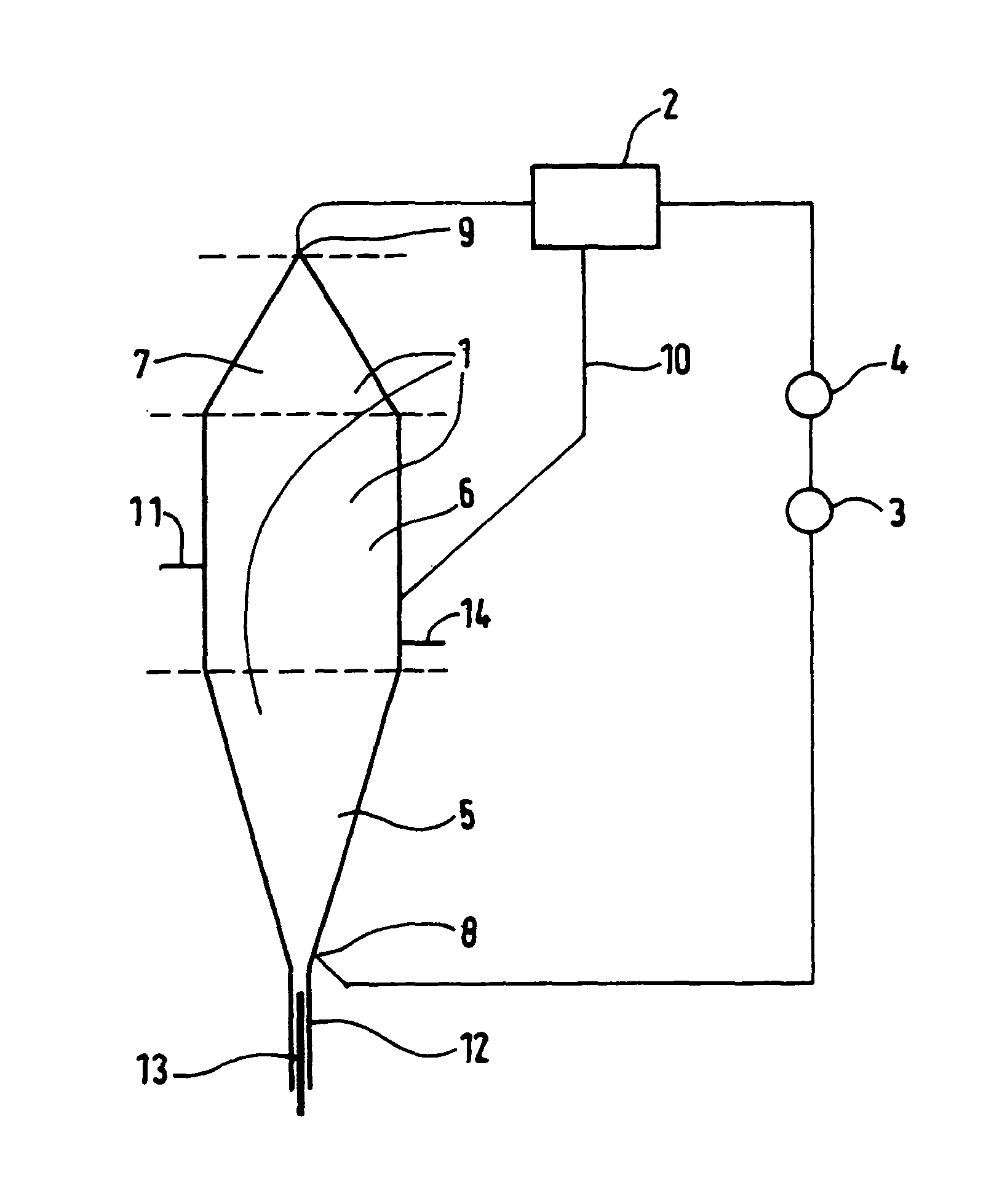
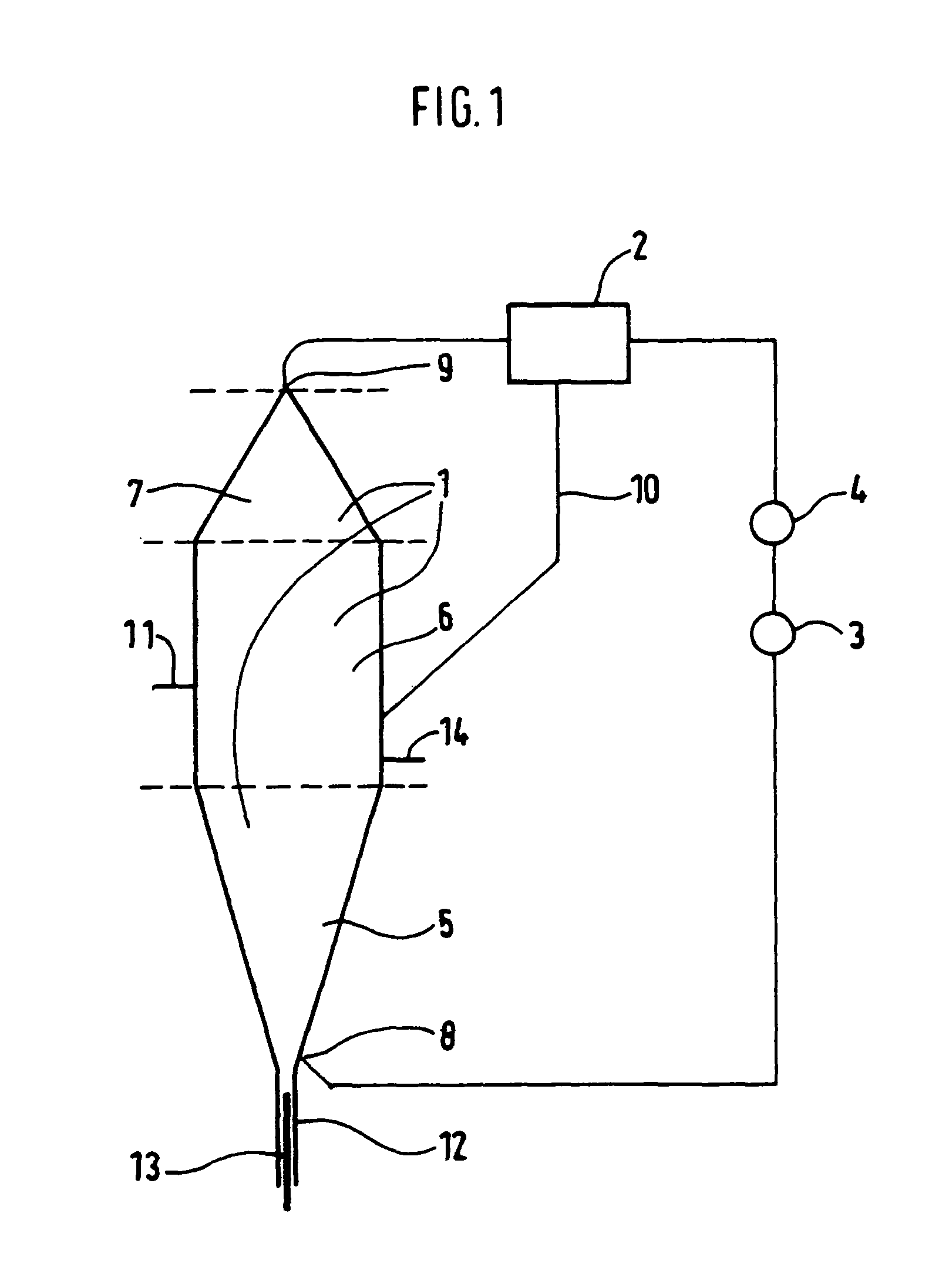
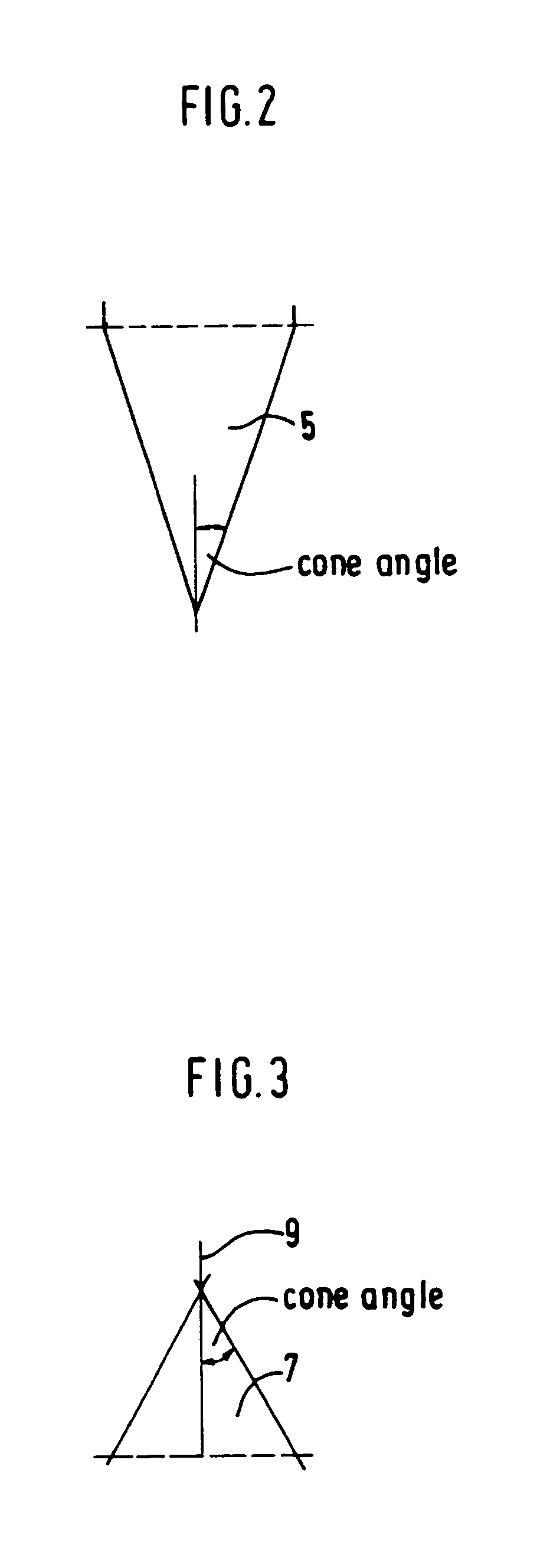
Reactor assembly for the production of polymers including a fluidized bed reactor (1) comprising a bottom zone (5), a middle zone (6) and an upper zone (7), an inlet (8) for the fluidization gas located in the bottom zone (5), an outlet (9) for the fluidization gas located in the upper zone (7); the outlet (9) for the fluidization gas being coupled with the fluidized bed reactor (1) via inlet (8) via a gas circulation line; means for separation of solids from gas (2) being connected to said gas circulation line; the equivalent cross-sectional diameter of the upper zone (7) being monotonically decreasing with respect to the flow direction of the fluidization gas through the fluidized bed reactor; the middle zone (6) having an essentially constant equivalent cross-sectional diameter with respect to the flow direction of the fluidization gas through the fluidized bed reactor; the equivalent cross-sectional diameter of the bottom zone (5) being monotonically increasing with respect to the flow direction of the fluidization gas through the fluidized bed reactor; characterized in that the ratio of the height of the fluidized bed reactor to the equivalent cross-sectional diameter of the middle zone of the fluidized bed reactor is from 2 to 10; and whereby said upper zone (7) is directly connected to said middle zone (6).

Description

[0001]The invention relates to a fluidized-bed reactor assembly for the polymerisation of olefinic monomer(s), and to multi reactor assemblies comprising at least one fluidized bed reactor.BACKGROUND[0002]Gas phase reactors are commonly used for the polymerization of olefins such as ethylene and propylene as they allow relative high flexibility in polymer design and the use of various catalyst systems. A common gas phase reactor variant is the fluidized bed reactor. In polyolefin production, olefins are polymerized in the presence of a polymerization catalyst in an upwards moving gas stream. The fluidization gas is removed from the top of the reactor, cooled in a cooler, typically a heat exchanger, re-pressured and fed back into the bottom part of the reactor. The reactor typically contains a fluidized bed comprising the growing polymer particles containing the active catalyst located above a distribution plate separating the bottom and the middle zone of the reactor. The velocity o...

Claims


Application Information

Patent Timeline
Patent Type & Authority Patents(United States)
IPC IPC(8): C08F2/01C08F210/16C08F110/06B01J19/24B01J8/38B01J8/18B01J8/24C08F2/34C08F10/02C08F210/08
CPCB01J8/1872B01J8/1827B01J8/388B01J19/2465C08F110/06C08F210/16B01J2208/00274B01J2219/0004B01J2219/00254B01J2219/1947B01J8/18B01J8/24B01J8/38B01J19/24
Inventor WEICKERT, GUNTERERIKSSON, ERIKBERGSTRA, MICHIELNYFORS, KLAUS
Owner BOREALIS AG
Learn More