Optical tissue sectioning using full field optical coherence tomography

a technology of optical coherence tomography and optical tissue, applied in the field of biomedical imaging, can solve the problems of mainly limited morphology and architecture information given by standard ff-oct images, and it is more difficult to get sharp images at the cellular level of virtual thin slices at large depths, and achieve the effect of easy combination and/or separation

Active Publication Date: 2015-11-10
LLTECH MANAGEMENT
View PDF8 Cites 22 Cited by
  • Summary
  • Abstract
  • Description
  • Claims
  • Application Information

AI Technical Summary

Benefits of technology

[0017]In the multimodal optical sectioning microscope of the first aspect, the full-field OCT system and the supplementary full-field optical sectioning imaging system are combined to share at least partially a common optical imaging channel. It is thus possible to provide additional contrasts in an FF-OCT system while keeping a compact apparatus implementing a parallel detection of each point of the image. Further, sharing the same microscope objective enables providing images of the same zone of the sample, with the same transversal resolution and different contrasts.
[0019]According to another embodiment, the supplementary full-field optical sectioning imaging system and the FF-OCT system have different illumination sub-system and / or detection sub-system. Typically, the useful illumination bandwidth for a FF-OCT system is in the near infrared (600-900 nm) as a good compromise between penetration depth in biological samples and optical resolution, whereas the excitation / emission spectra of a lot of fluorophores is in the range 350-600 nm. When using for the full-field OCT system and the full-field optical sectioning system different illumination sub-system and / or detection sub-system, it will be very easy to combine and / or separate the respective light beams in both systems using dichroic beamsplitters.

Problems solved by technology

Concerning the other tissues of the human body that are dense and exhibit a very large scattering cross-section it is more difficult to get sharp images at the cellular level of virtual thin slices at large depths.
However, compared to histology slides, which are the “Gold Standard” in pathology, the information given by standard FF-OCT images is mainly limited to morphology and architecture.
The contrast risen by the FF-OCT technique on particular metabolic structures such as tumorous areas of a tissue, is not always enough to perform an accurate diagnostic.
However, OCT techniques, including the FF-OCT technique, are not compatible with fluorescence microscopy as light coming from the emission of fluorescence of the sample is incoherent with the light source.
Consequently, the optical path length equalization between the two interferometric arms is not possible anymore, and interference signals necessary to coherence tomography techniques can not be obtained.

Method used


Image

  • Optical tissue sectioning using full field optical coherence tomography
  • Optical tissue sectioning using full field optical coherence tomography
  • Optical tissue sectioning using full field optical coherence tomography

Examples


first embodiment

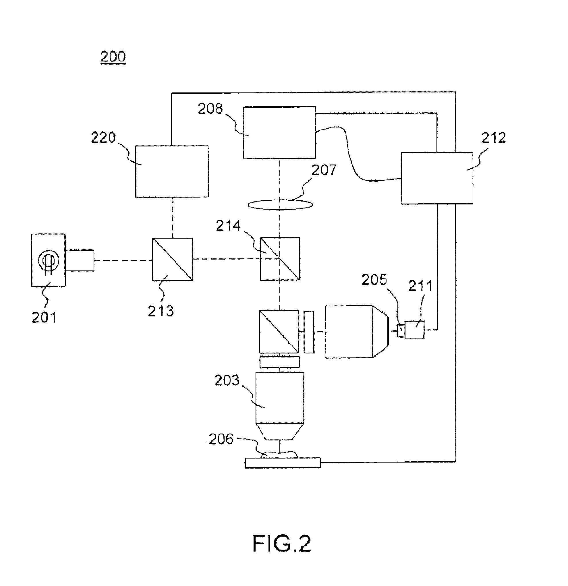
[0051]FIG. 4 shows an experimental system according to a multimodal FF-OCT system according to the present disclosure incorporating a structured illumination microscope. The system 400 is a Full-Field Optical Coherence Tomography microscope including an additional sectioning capability for providing both a tomographic image and a fluorescent image of a sample.

[0052]The microscope 400 comprises a source 401 which is spatially and temporally low coherent, typically a halogen or xenon lamp or a LED or combination of LEDS, and an imaging interferometer comprising a beamsplitter 402, typically a non-polarizing beamsplitter cube, defining two interferometric arms. Both arms include a microscope objective 403 and 404 of the same characteristics. In one arm, further named the reference arm, a uniform reflective surface 405 is positioned at the focal plane of the objective and linked to an oscillator 411, allowing modulation of the optical path length of the reference arm, e.g. a piezo elect...

second embodiment

[0064]FIG. 6 shows an experimental system according to a multimodal FF-OCT system incorporating a structure illumination module. The system is similar to the system of FIG. 4 except for the illumination subsystem and detection sub system. In the case of fluorescence imaging using SIM, the detected photons are the fluorescence photons added to the FFOCT photons. For optimizing the sensitivity of both techniques, it may be advantageous to separate the two imaging channel at the illumination and detection levels. In this way, one—or more—source 623 of optimal characteristics for fluorescence excitation, for example with a spectrum corresponding to the excitation spectrum of the fluorescent dye used, is used to illuminate the sample 606 through a mask 621 of variable spatial transmittance, e.g a grid, modulated by the oscillator 622, as already described in FIG. 4. The grid 621 is conjugated with the sample imaging plane using optics 630 and 603, and this SIM illuminator is inserted int...


PUM


Abstract

According to a first aspect, the invention relates to a multimodal optical sectioning microscope (200, 400, 600) for full-field imaging of a volumic and scattering sample comprising:—a full-field OCT system for providing an image of a first section in depth of the sample comprising an illumination sub-system (201, 401, 601) and a full-field imaging interferometer with a detection sub system (208, 408, 608) and an optical conjugation device for optically conjugating the sample and said detection sub system, wherein said optical conjugation device comprises a microscope objective (203, 403, 603), —a supplementary full-field optical sectioning imaging system for providing a fluorescent image of a second section in depth of said sample comprising a structured illumination microscope with an illumination sub system (623), means (421, 422) for generating at the focal plane of said microscope objective of said full-field imaging interferometer a variable spatial pattern illumination and a detection sub system (624), optically conjugated with said focal plane of the microscope objective.

Description

BACKGROUND[0001]The present invention is in the technical field of biomedical imaging, more particularly in the technical field of optical microscopy and more particularly in the technical field of optical sectioning microscopy.[0002]Optical sectioning microscopy refers to the imaging of a section in depth of a sample, the section being in the focal plane of a microscope objective, while removing the background in the image due to out-of-focus light and scatter. When microscopy is applied to biological samples such as cells or tissues which exhibit strong scattering, optical sectioning dramatically improves the quality of the images obtained. It is thus of paramount importance for biological as well as medical purposes. Among the techniques that are used for high resolution imaging in the micrometer range, confocal microscopy (see for example U.S. Pat. No. 3,013,467—Minsky) and non-linear microcopies (e.g. two Photon—see for example Denk W, Strickler J, Webb W (1990). “Two-photon la...

Claims


Application Information

Patent Timeline
Patent Type & Authority Patents(United States)
IPC IPC(8): H04N9/47H04N7/18A61B5/00
CPCH04N7/18A61B5/0066A61B5/0068G01B9/02041G01B9/02091G02B21/14G02B21/16G02B21/367
Inventor BOCCARA, ALBERT CLAUDEHARMS, FABRICELE CONTE CHRESTIEN DE POLY, BERTRAND
Owner LLTECH MANAGEMENT
Why Eureka
Try Eureka