
Communications terminal, communications method, and program and integrated circuit for controlling a reproduction delay time in distributing a stream

a communication terminal and stream technology, applied in the field of communication terminals and communications methods, can solve problems such as lower transmission quality than expected, and achieve the effect of improving stream data quality

Active Publication Date: 2015-11-10
PANASONIC INTELLECTUAL PROPERTY MANAGEMENT CO LTD
View PDF20 Cites 1 Cited by
  • Summary
  • Abstract
  • Description
  • Claims
  • Application Information

AI Technical Summary

Benefits of technology

This approach ensures high-quality reproduction of stream data by accounting for varying network delays, minimizing jitter and maintaining transmission quality across the ALM tree.

Problems solved by technology

In the case where delays are different with each other between the terminals when this technique is applied to one of the second and the third techniques, however, the differences could develop a problem in that the resulting transmission quality would be lower than expected.

Method used


Image

  • Communications terminal, communications method, and program and integrated circuit for controlling a reproduction delay time in distributing a stream
  • Communications terminal, communications method, and program and integrated circuit for controlling a reproduction delay time in distributing a stream
  • Communications terminal, communications method, and program and integrated circuit for controlling a reproduction delay time in distributing a stream

Examples


embodiment 1

[Embodiment 1]

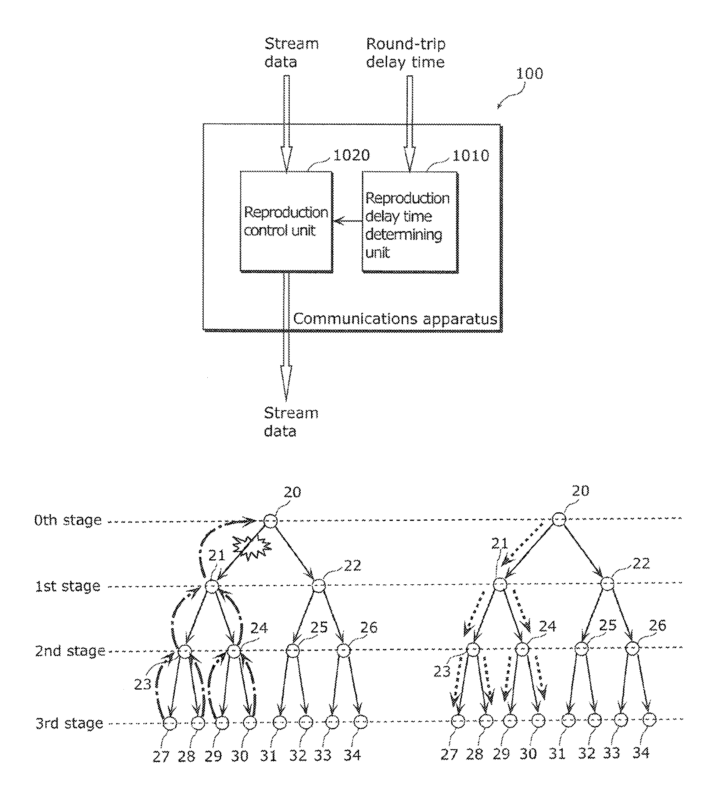
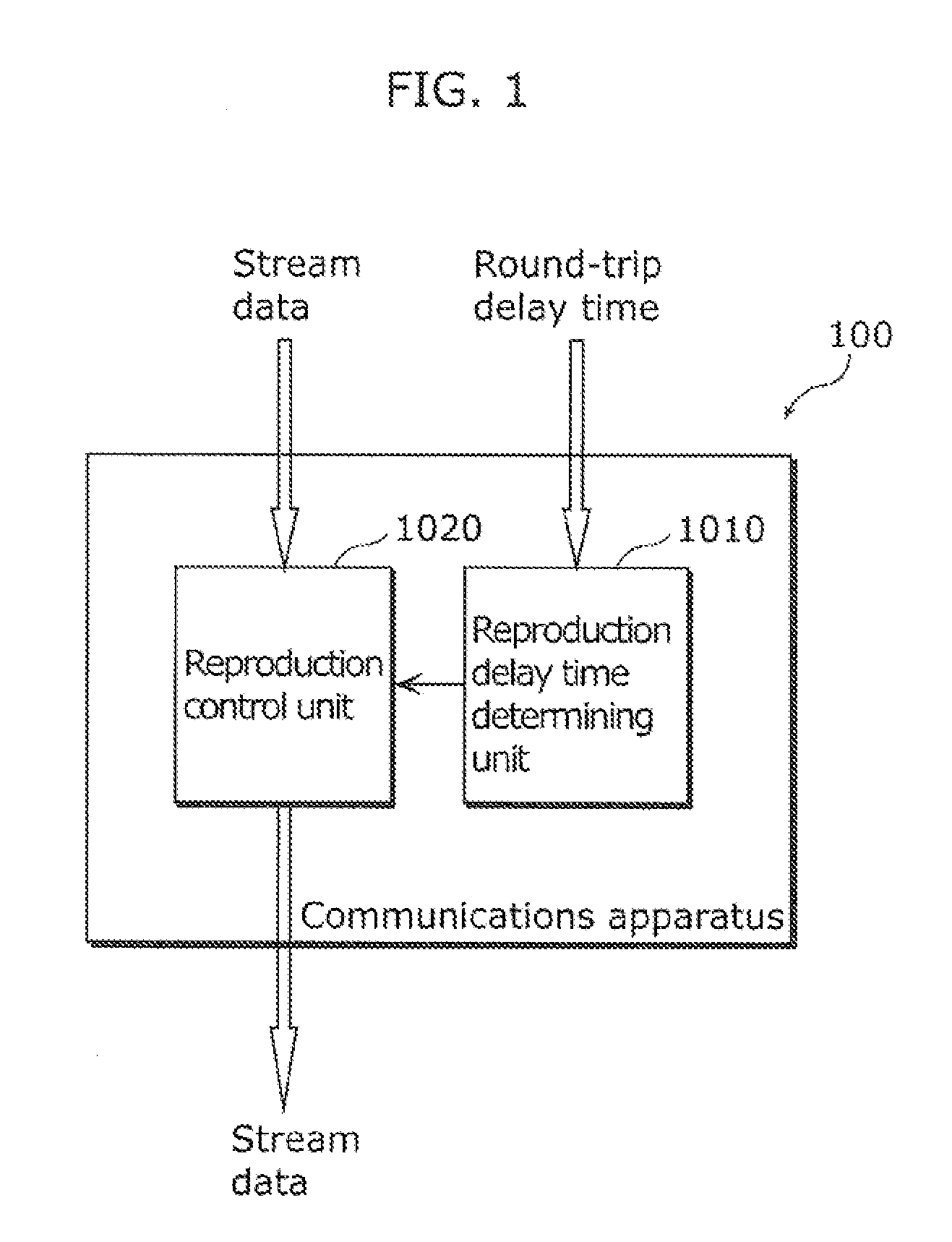
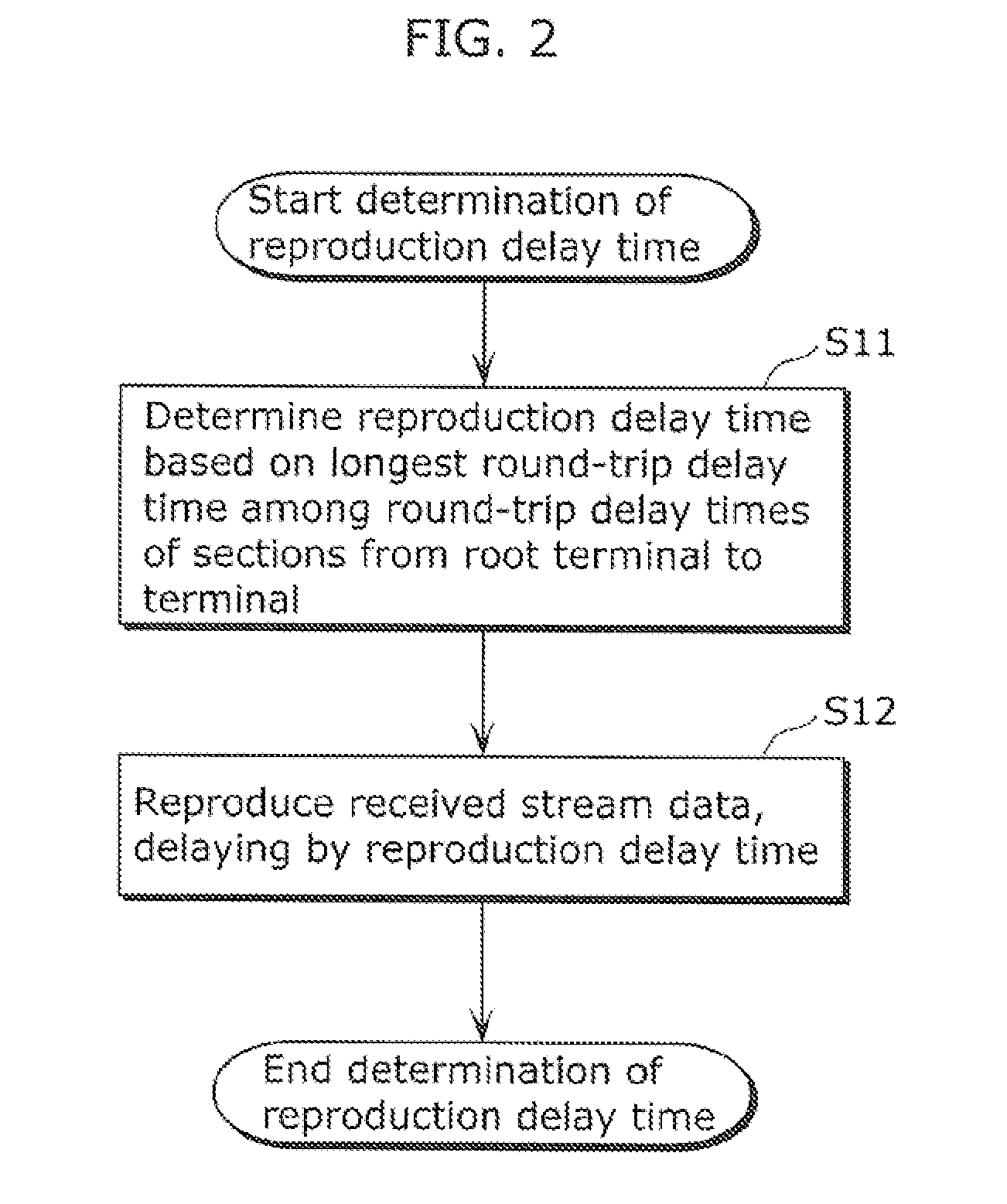
[0070]Described hereinafter are a structure and an operation of a communications terminal 100 according to Embodiment 1 of the present invention, with reference to FIGS. 1 and 2. It is noted that FIG. 1 is a functional block diagram of the communications terminal 100. FIG. 2 is a flowchart showing the operation of the communications terminal 100.

[0071]As shown in FIG. 1, the communications terminal 100 according to Embodiment 1 includes a reproduction delay time determining unit 1010 and a reproduction control unit 1020. The communications terminal 100 is one of communications terminals (not shown in FIG. 1) each of which receives stream data distributed from a root terminal and reproduces the stream data. The communications terminals form an ALM tree. On the ALM tree, each of the communications terminals has one parent terminal and zero or more child terminals, so that the retransmission data of the stream data is sequentially transmitted from the parent terminal to t...

embodiment 2

[Embodiment 2]

[0129]Described next is a structure and an operation of a communications terminal according to Embodiment 2. It is noted that the details shared between Embodiments 1 and 2 shall be omitted, and the differences may be mainly described. The communications terminal according to Embodiment 2 has the communications terminal 100 in FIG. 1 include a loss rate managing unit and a loss rate measuring unit. Furthermore, the reproduction delay time determining unit 401 in Embodiment 2 employs a technique of determining the reproduction delay time differs specifically different from that employed in Embodiment 1.

[0130]The loss rate measuring unit measures a loss rate of the stream data between a terminal and the parent terminal. Specifically, the loss rate measuring unit may calculate the Packet Error Rate (PER) of the received stream data with reference to the sequence number of the TCP header.

[0131]The loss rate managing unit receives, from the parent terminal, a loss rate noti...

embodiment 3

[Embodiment 3]

[0135]The present invention may be provided in a form of a program executed by a computer implementing communications methods in Embodiments 1 and 2, as well as the communications terminals and the communications methods in Embodiments 1 and 2.

[0136]FIGS. 11A to 11C show how a computer system executes the communications methods according to Embodiments 1 and 2 using a flexible disk floppy disk (FD) which stores the methods.

[0137]FIG. 11A shows a physical format of a magnetic disk used as a storage medium body. FIG. 11B shows a magnetic disk MD, and an elevated view and a cross-sectional view of a casing F holding the magnetic disk MD. FIG. 11C shows how a program is stored on a flexible disk and is reproduced.

[0138]The flexible disk FD includes the magnetic disk MD; namely a storage medium body, and the casing F holding the magnetic disk MD. The surface of the magnetic disk MD has tracks Tr concentrically formed from the outer periphery to the inner periphery. Each of ...


PUM


Abstract

A communication terminal (100) is one of communication terminals each having one parent terminal and zero or more child terminals. The communication terminals form an Application Layer Multicast (ALM) tree to sequentially distribute retransmission data of stream data from the parent terminal to the child terminal. The communications terminal (100) includes: a reproduction delay time determining unit (1010) determining a reproduction delay time based on a longest round-trip delay time among round-trip delay times of sections between a root terminal and the communications terminal (100), each of the round-trip delay times being required for transmission and reception of data through one of the sections between two neighboring terminals of the communications terminals on the ALM tree; and a reproduction control unit (1020) reproducing the stream data received from the root terminal, with the stream data delayed by the reproduction delay time determined by the reproduction delay time determining unit (1010).

Description

TECHNICAL FIELD[0001]The present disclosure relates to a communications terminal and a communications method for controlling a reproduction delay time in distributing a stream via an Application Layer Multicast (ALM) tree.BACKGROUND OF INVENTION[0002]Background Art[0003]In image data (packet) transmission and reception between a transmitting terminal 11 and a receiving terminal 12 on the Internet, an image data loss (packet loss) could occur as shown in FIG. 12. Such an image data loss inevitably causes the receiving terminal 12 to reproduce jittering images and audios. In order to prevent the jittery images and audios from occurring, the lost packet needs to be retransmitted to the transmitting terminal 11.[0004]Thus, as shown in FIG. 13, the receiving terminal 12 requests the transmitting terminal 11 to retransmit a lost image packet (p2). In response to the request from the receiving terminal 12, the transmitting terminal 11 usually retransmits the corresponding packet (p2), as s...

Claims


Application Information

Patent Timeline
Patent Type & Authority Patents(United States)
IPC IPC(8): G06F15/16H04N21/6405H04L12/18H04L47/32
CPCH04L12/1854H04L12/1868H04N21/6405
Inventor BADUGE, THILMEE MALINDAMURAMOTO, EIICHI
Owner PANASONIC INTELLECTUAL PROPERTY MANAGEMENT CO LTD
Learn More