
Microwave driven electrodeless lamp comprising magnetron without forced convective cooling

a technology of magnetron and electrodeless lamps, which is applied in the field of light sources, can solve the problems of losing the efficiency of microwave generation, still dissipating a considerable amount of heat, and being susceptible to overheating

Inactive Publication Date: 2015-10-13
CERAVISION LTD
View PDF10 Cites 1 Cited by
  • Summary
  • Abstract
  • Description
  • Claims
  • Application Information

AI Technical Summary

Benefits of technology

The present invention provides a new type of LUWPL that does not require forced convective cooling. This means that the cooling system is not needed, which reduces the complexity of the device.

Problems solved by technology

Whilst our LUWPL technology is in generally efficient in terms of lumens of light produced per watt of electricity consumed in its operation, they still dissipate a considerable wattage of heat that must be dissipated, to avoid components overheating.
Magnetrons are particularly susceptible to overheating, significantly losing efficiency of microwave generation if their magnets are overheated.

Method used


Image

  • Microwave driven electrodeless lamp comprising magnetron without forced convective cooling
  • Microwave driven electrodeless lamp comprising magnetron without forced convective cooling
  • Microwave driven electrodeless lamp comprising magnetron without forced convective cooling

Examples


Embodiment Construction

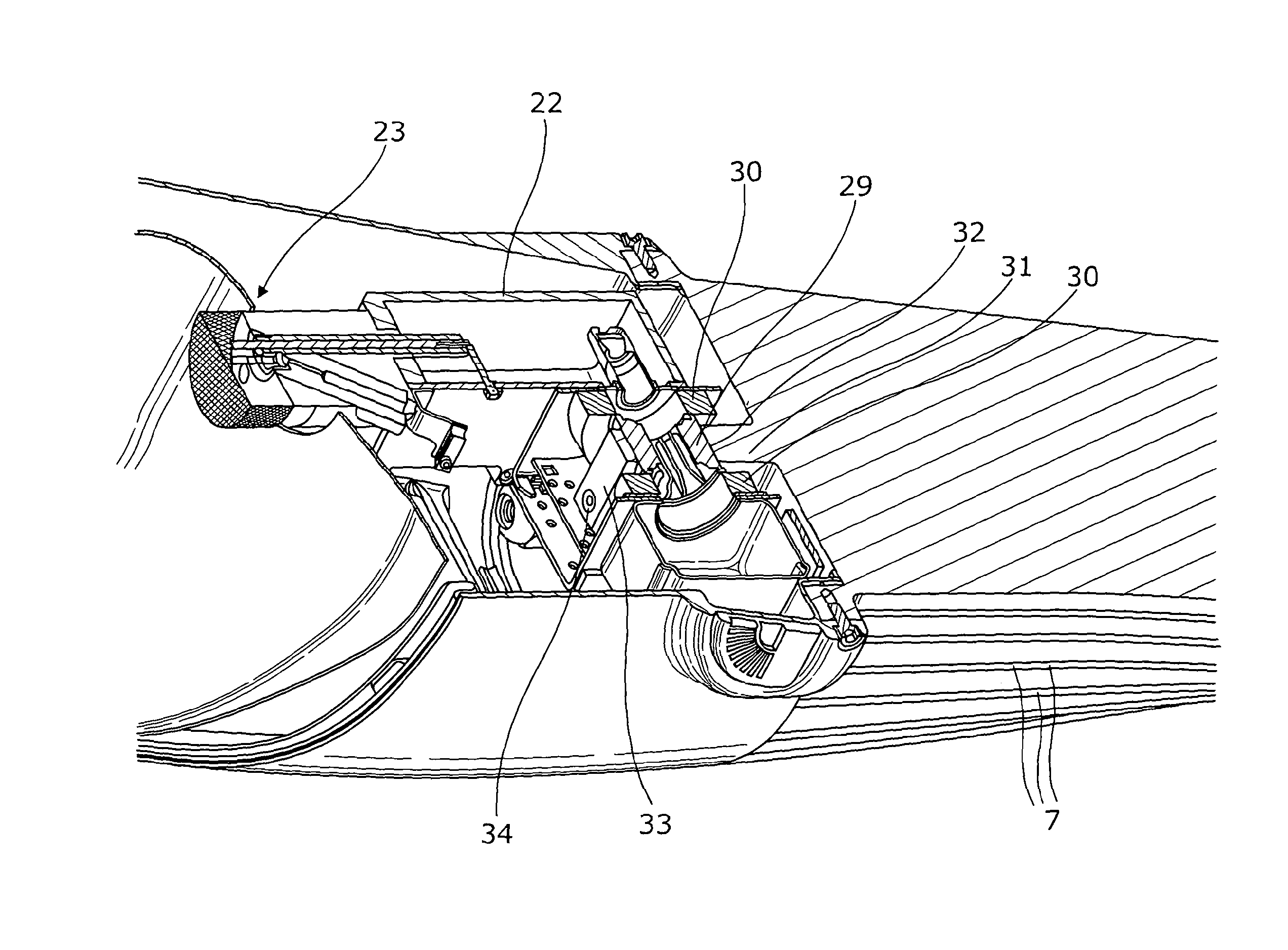
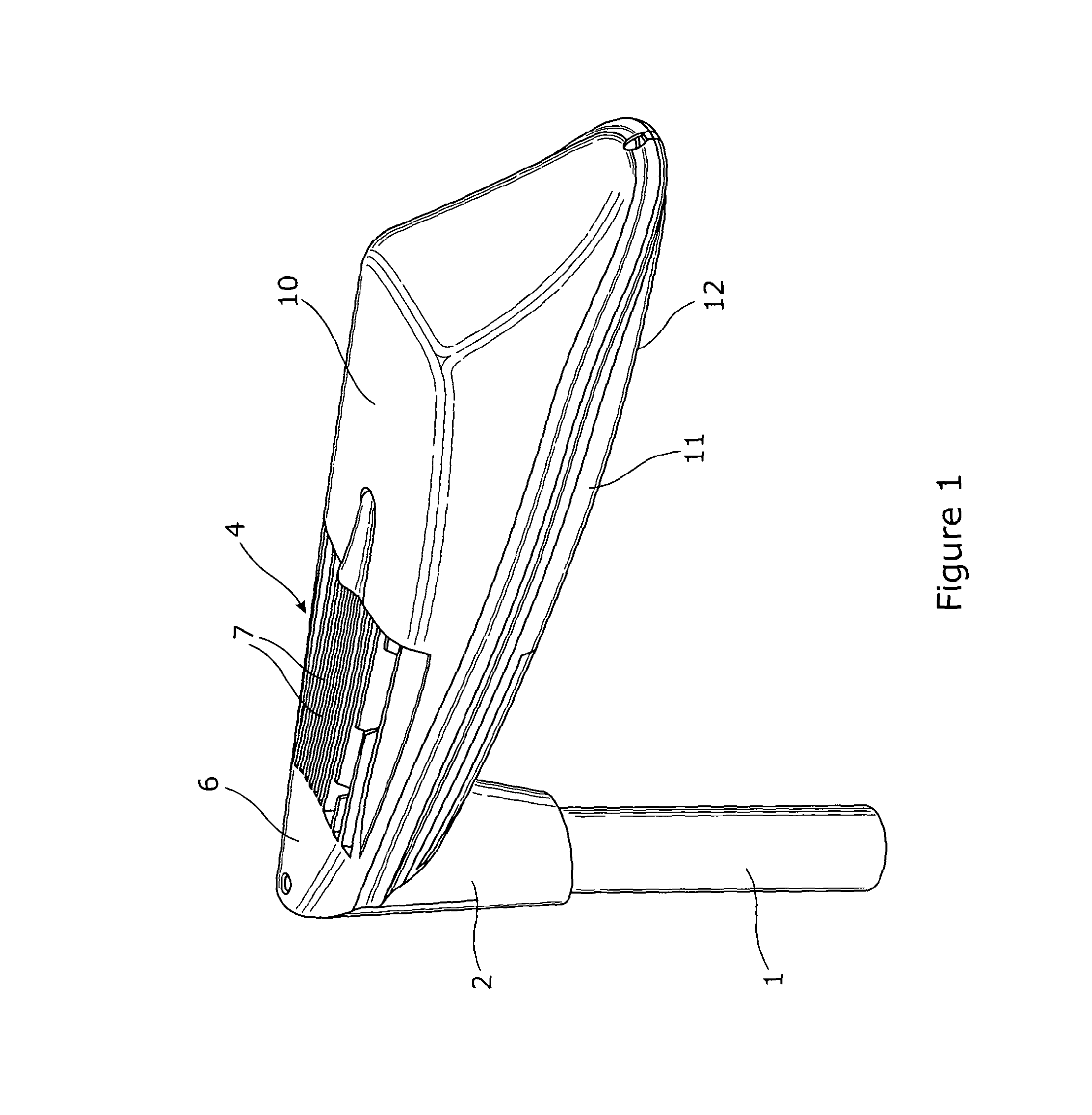
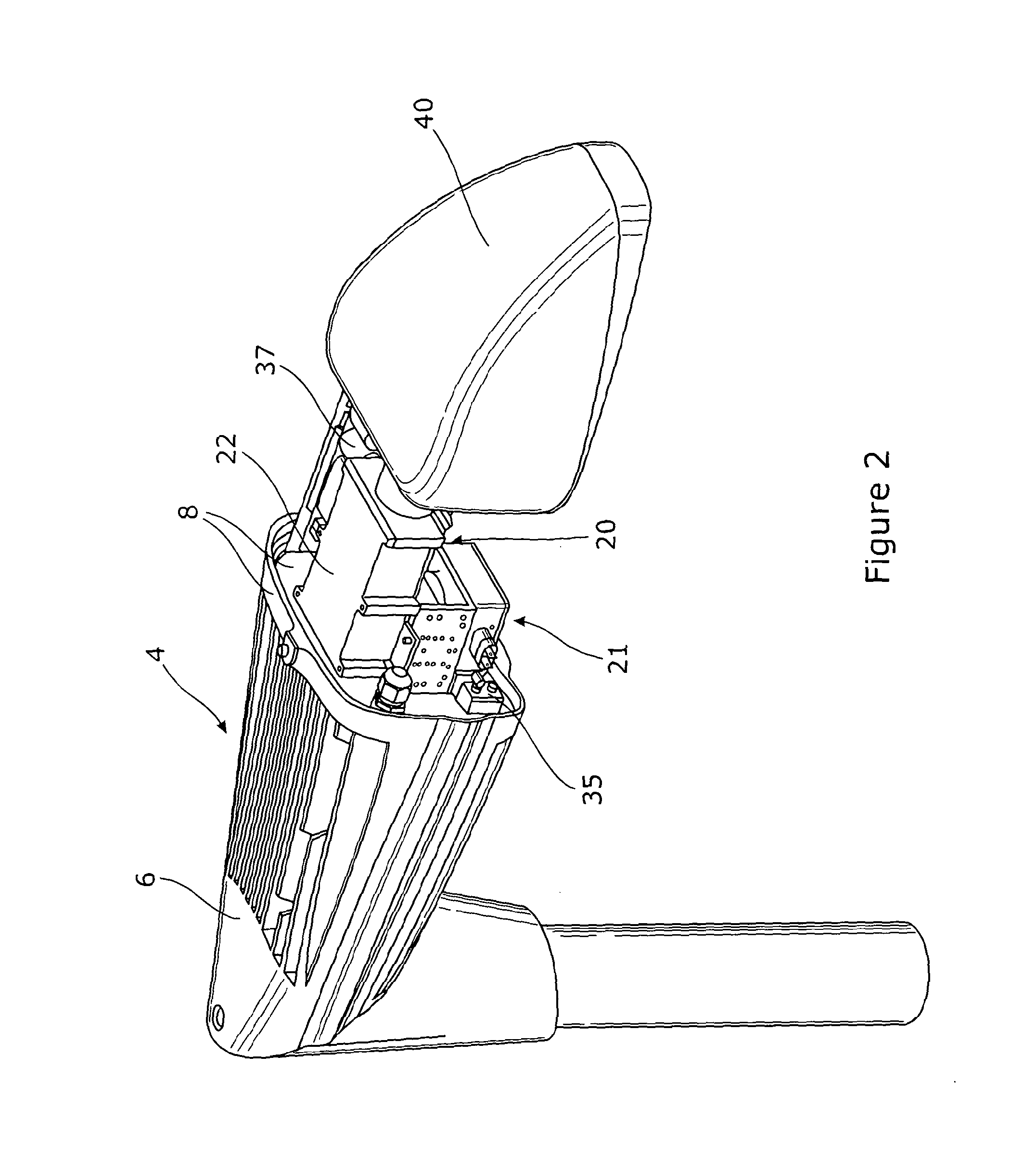
[0110]Referring first to FIGS. 1 to 10 of the accompanying drawings, a Lucent Waveguide Plasma Light Source is configured as a street light, for support on a lamp standard 1. The LUWPL has a lamp standard adapter 2 presenting a face 3 angled at 45°. In a non-shown alternative, the adapter may be substituted for a wall bracket also presenting a 45° face. A heat dissipating support structure 4 has a complementarily angled face 5. The adapter 2 and the structure 4 are bolted together with their 45° faces abutting.

[0111]The structure 4 is an integral aluminium casting having a boss 6 presenting the angled face 5, a series of substantially vertically oriented fins 7 and a hub 8. The fins close together in their extent from the hub to the flange and also taper in their height. Within them, the fins define a vertically extending convective airway 9, indicated in FIG. 3 by airflow arrows.

[0112]At the hub 8, the contour of the fins is continued by an upper cover 10 and a lower cover 11, in w...


PUM


Abstract

A LUWPL luminaire has a housing with a lower transparent closure and a heat dissipating top of cast aluminum. This has a suspension eye. The housing has an upper flange via which it is bolted with the interposition of a seal to a underside rim of the top. Within the rim, the underside is substantially flat, with a magnetron attachment boss and other attachment points. A magnetron is supported by being clamped by a saddle to the attachment boss at the magnetron's anode. The magnetron is fast with a transition box and a crucible support block. A bracket fixed to certain of the attachment points extends down from the top is screwed to the transition box. Thus the LUWPL parts are securely supported below the top.

Description

CROSS REFERENCE TO RELATED APPLICATION[0001]This application is for entry into the U.S. National Phase under §371 for International Application No. PCT / GB2012 / 000764 having an international filing date of Oct. 5, 2012, and from which priority is claimed under all applicable sections of Title of the United States Code including, but not limited to, Sections 120, 363, and 365(c), and which in turn claims priority under 35 USC 119 to United Kingdom Patent Application No. 1117409.1 filed on Oct. 7, 2011 and United Kingdom Patent Application No. 1206554.6 filed on Apr. 13, 2012.BACKGROUND OF THE INVENTION[0002]1. Field of the Invention[0003]The present invention relates to a light source.[0004]We have developed technology for the production of light via plasma excitation in a Lucent Waveguide electromagnetic Wave Plasma Light source. We refer to this technology as LUWPL technology.[0005]2. Description of the Related Art[0006]We define a LUWPL source as having:[0007]a fabrication of solid...

Claims


Application Information

Patent Timeline
IPC IPC(8): H01J1/02F21V29/74H01J7/24H01J65/04H01J19/36H01J61/52H01K1/58F21S8/08F21V29/507
CPCH01J19/36F21V29/74H01J65/044H01J65/04F21V29/507F21S8/086
Inventor CARPENTER, PAULNEATE, ANDREW SIMON
Owner CERAVISION LTD
Learn More