Digital switched mode voltage regulator
a voltage regulator and digital switch technology, applied in the direction of electrical variable regulation, efficient power electronics conversion, instruments, etc., can solve the problem that the integrated portion of the regulation loop may not be able to respond to small or moderate load fluctuations at the output voltage, and achieve the effect of improving loop stability, ensuring circuit complexity, and maintaining circuit complexity, area and power consumption at an acceptable level
- Summary
- Abstract
- Description
- Claims
- Application Information
AI Technical Summary
Benefits of technology
Problems solved by technology
Method used
Image
Examples
first embodiment
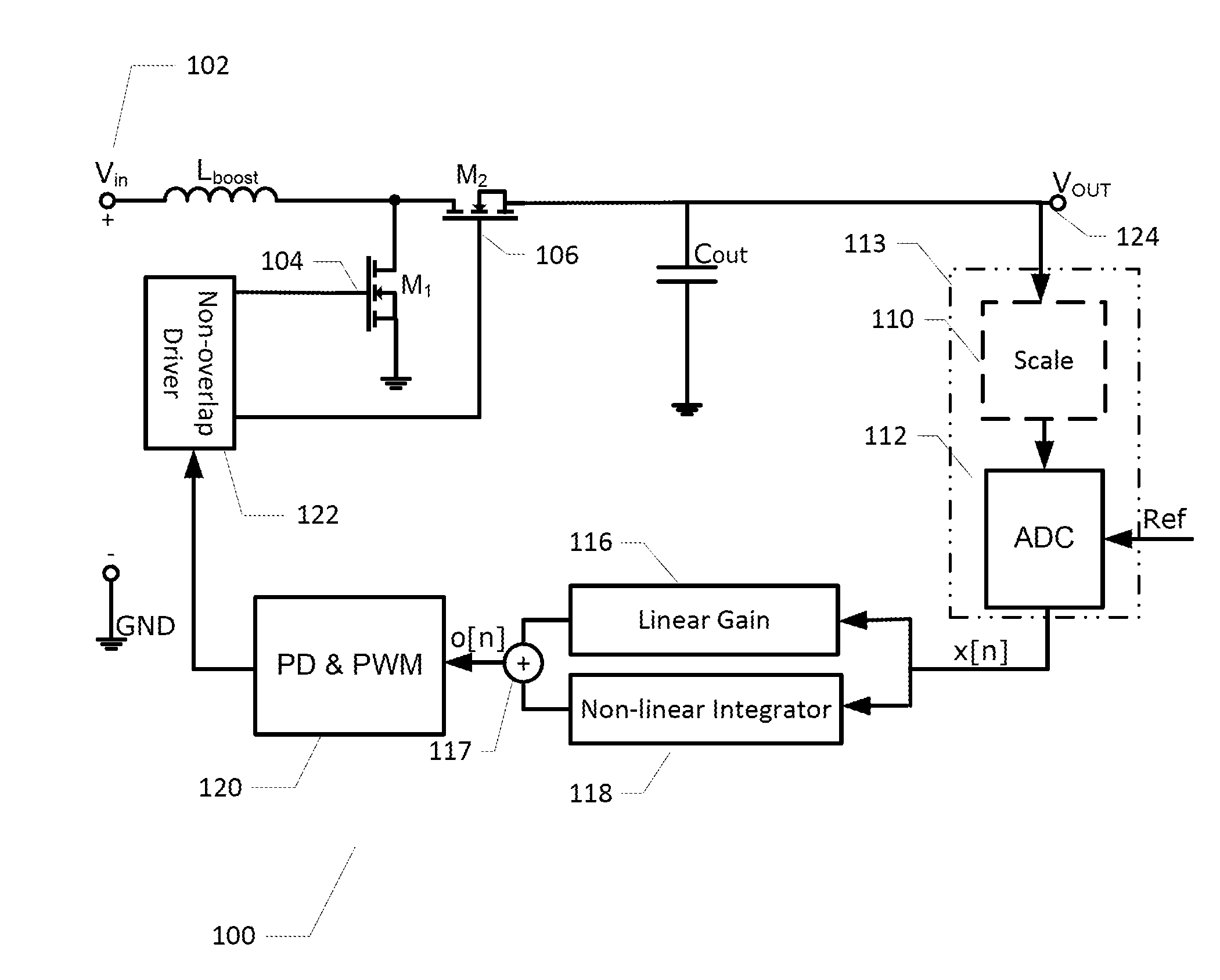
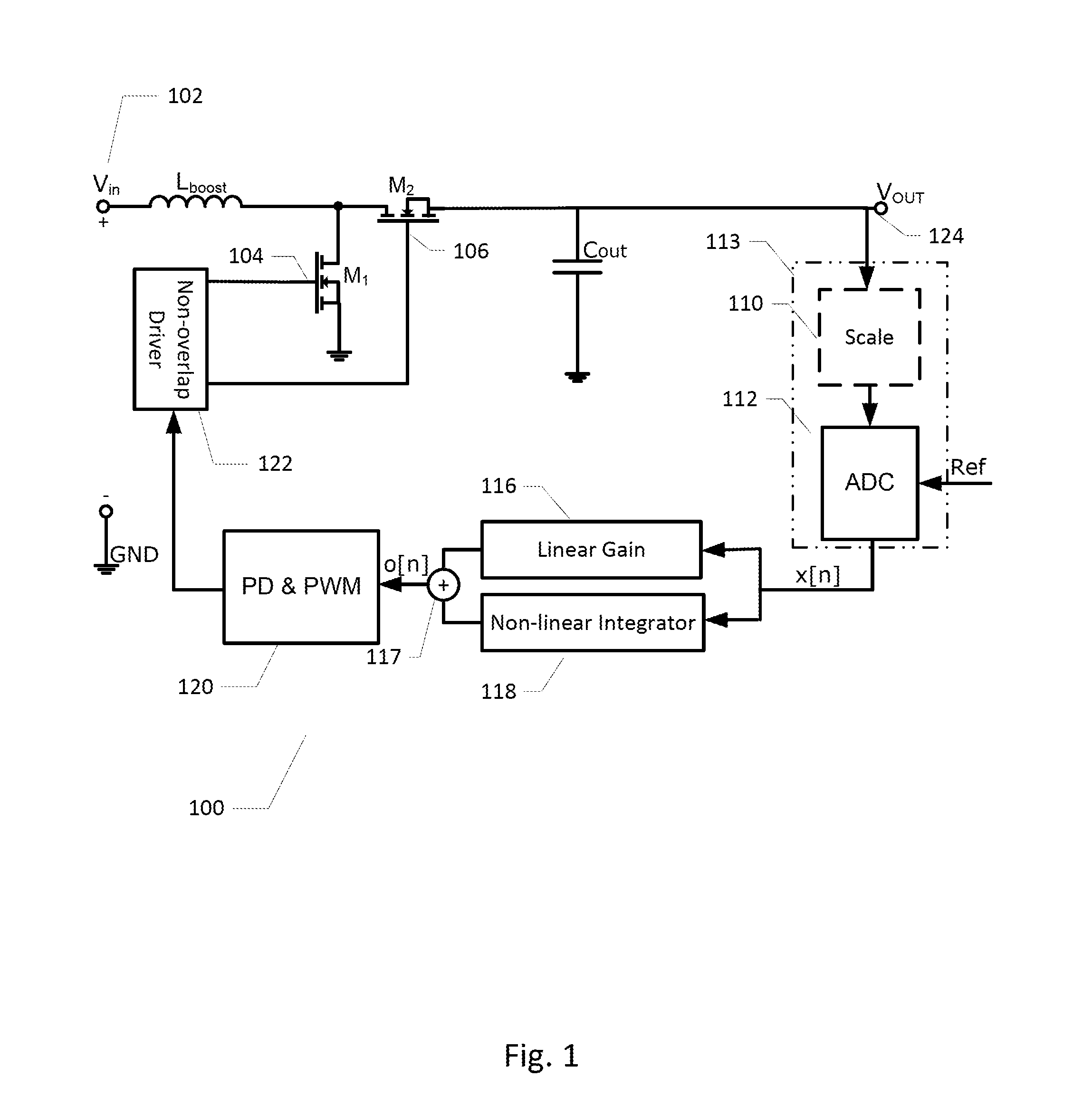
[0035]FIG. 1 illustrates schematically a boost-type of switched mode voltage regulator circuit 100 in accordance with the invention. The switched mode voltage regulator circuit 100 comprises an input terminal 102 for receipt of a regulator input voltage Vin for example a DC power rail or a DC voltage from a rechargeable battery. An output terminal 124 is electrically coupled to an output capacitor Cout for supply of a DC output voltage VOUT. A converter inductance is provided by an inductor Lboost which is electrically coupled to the regulator input voltage such that Lboost is charged with energy from Vin through a first semiconductor switch, formed by CMOS transistor M1, in a first regulator mode. In the first regular mode, the CMOS transistor M1 is placed in a conducting state or on-state by non-overlapping switch driver 122 by applying an appropriate gate voltage to gate terminal 104 of M1. The non-overlapping switch driver 122 furthermore places a second semiconductor switch, in...
second embodiment
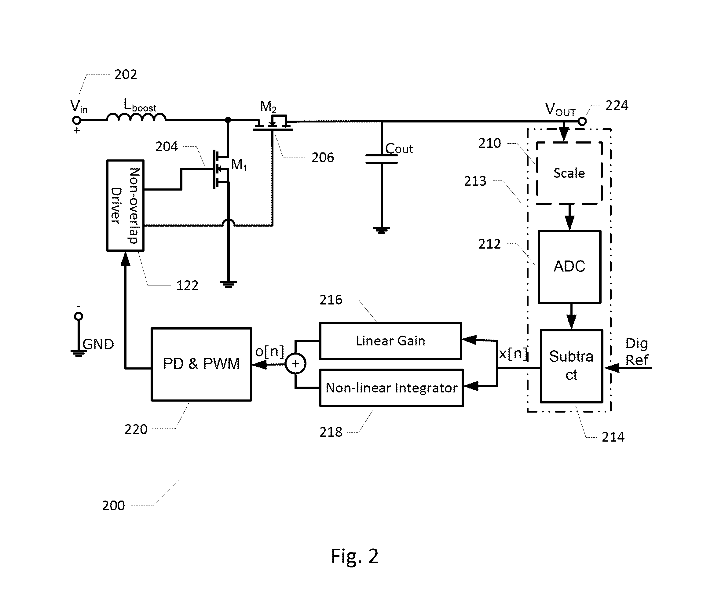
[0041]FIG. 2 illustrates schematically a boost-type of switched mode voltage regulator circuit 200 in accordance with the invention. The switched mode voltage regulator circuit 200 shares numerous features with the above described voltage regulator circuit 100 and corresponding features have been provided with corresponding reference numerals to assist comparison. The main difference is how the digital error signal x[n] is generated. In the present embodiment, the reference voltage is provided in digital representation, i.e. as a digital reference voltage or number, indicated by arrow “Dig Ref” to the error signal generator 213. An analog-to-digital converter 212, which may have similar characteristics to the above-discussed converter 112, is operatively coupled to the DC output voltage to provide a digital / digitized DC output voltage number or signal. The digitized DC output voltage signal is applied to a first input of a digital subtractor 214 while the digital reference voltage i...
PUM
 Abstract
Description
Claims
Application Information
 - R&D
- Intellectual Property
- Life Sciences
- Materials
- Tech Scout
- Unparalleled Data Quality
- Higher Quality Content
- 60% Fewer Hallucinations
Browse by: Latest US Patents, China's latest patents, Technical Efficacy Thesaurus, Application Domain, Technology Topic, Popular Technical Reports.
© 2025 PatSnap. All rights reserved.Legal|Privacy policy|Modern Slavery Act Transparency Statement|Sitemap|About US| Contact US: help@patsnap.com


