
System and method for identifying exploitable weak points in a network

a network and exploitable weak point technology, applied in the field of system and method for identifying exploitable weak points in a network, can solve problems such as limiting the effectiveness of active vulnerability scanners, denying access, and illegal or unauthorized users exploiting vulnerabilities

Active Publication Date: 2015-05-26
TENABLE INC
View PDF187 Cites 23 Cited by
  • Summary
  • Abstract
  • Description
  • Claims
  • Application Information

AI Technical Summary

Benefits of technology

[0010]According to one aspect of the invention, the system and method described herein may have one or more passive scanners observe traffic traveling in the network to identify potential vulnerabilities in the network and detect activity that may potentially target or otherwise attempt to exploit vulnerabilities in the network. The passive scanners may generally observe the traffic traveling across the network to reconstruct one or more sessions occurring in the network, which may then be analyzed to identify potential vulnerabilities in the network and / or activity targeting the identified vulnerabilities. As such, the passive scanners may monitor the network in real-time to detect any potential vulnerabilities in the network, identify changes in the network, or otherwise provide visibility into the network and the activity that occurs therein. For example, in one implementation, the passive scanners may be deployed at a network hub, a spanned switch port, a network tap, a network choke point, a dial up node, a server farm, behind a firewall, or any other suitable location that enables the passive scanners to observe incoming and outgoing traffic in the network. In one implementation, the passive scanners may generally be deployed on any suitable server or other host in the network.

Problems solved by technology

In many network environments, illegal or unauthorized users may exploit vulnerabilities in the network to gain access, deny access, or otherwise attack systems in the network.
Accordingly, physical limitations associated with the network typically limit the effectiveness for active vulnerability scanners because only devices that can communicate with the active vulnerability scanners can be audited, while actively scanning networks distributed over large areas or having large numbers of devices may take long amounts of time.
Further, in scenarios where one or more of the routers have firewalls that screen or otherwise filter incoming and outgoing traffic, the active vulnerability scanner may generate incomplete results because the firewalls may prevent the active vulnerability scanner from auditing hosts or other devices behind the firewalls.
Furthermore, active vulnerability scanners typically create audit results that become stale over time because the audit results describe a static state for the network at a particular point in time.
Thus, an active vulnerability scanner would likely fail to detect that hosts have been added or removed from the network following a particular active scan, whereby the audit results that active vulnerability scanners create tend to steadily decrease in value over time as changes to the network occur.
Furthermore, active vulnerability scanners can have the tendency to cause network disruptions during an audit.
For example, probing network hosts or other devices during an audit performed by an active vulnerability scanner may result in communication bottlenecks, processing overhead, and instability, among other potential problems in the network.
Thus, deployment locations, configurations, and other factors employed to manage networks can often interfere with obtaining suitable network auditing results using only active vulnerability scanners.
As such, existing systems that tend to rely entirely on active vulnerability scanners typically prevent the active vulnerability scanner from obtaining comprehensive information that describes important settings, configurations, or other information associated with the network.
In particular, malicious or unauthorized users often employ various techniques to obscure network sessions during an attempted breach, but active vulnerability scanners often cannot detect real-time network activity that may provide indications that the attempted breach is occurring.
For example, many backdoor and rootkit applications tend to use non-standard ports and custom protocols to obscure network sessions, whereby intruders may compromise the network while escaping detection.
Accordingly, although active vulnerability scanners typically employed in existing network security systems can obtain certain information describing the network, existing systems cannot perform comprehensive security audits to completely describe potential vulnerabilities in the network, build models or topologies for the network, or derive other information that may be relevant to managing the network.
Furthermore, in many instances, certain hosts or devices may participate in sessions occurring on the network, yet the limitations described above can prevent active vulnerability scanners alone from suitably auditing the hosts or devices.
However, even when employing passive vulnerability scanners in combination with active vulnerability scanners, the amount of data returned by the active vulnerability scanners and the passive vulnerability scanners can often be quite substantial, which can lead to difficulties in administrating the potentially large number of vulnerabilities and assets in the network.
For example, many network topologies may include hundreds, thousands, or even larger numbers of nodes, whereby suitably representing the network topologies in a manner that provides visibility into the network can be unwieldy.
More particularly, in an ideal world all vulnerabilities identified in a network would be patched in real-time, but most organizations tend to have limited resources and must rely on scheduled patch deployment, which may lead to difficulties in identifying high-value network clients that are subject to network attacks and servers (potentially already fully patched) that are managed with high-risk clients.
However, traditional network modeling solutions tend to suffer from various drawbacks that limit abilities to model network configurations and vulnerabilities.
For example, a Windows 2008 system may be fully patched but administered from a desktop that surfs the Internet and that has an unpatched web browser or other exploitable client software, which may raise network vulnerabilities that could escape detection under the techniques employed with existing network security systems.
In another example, configurations associated with firewalls, routers, switches, and other traffic management systems may be unavailable or outdated in certain cases, in which case any vulnerability modeling may fail to reflect a current network configuration state.
Moreover, many networks have flat configurations in which every system can access every other system from inside a firewall, which raises substantially different issues from a flat network in which only a small subset of systems (e.g., administrators) can access key servers.
Further still, current exploit and vulnerability modeling systems tends to be server-centric and therefore only model server exploits and vulnerabilities rather than combinations of client-side and server-side exploits and vulnerabilities.

Method used


Image

  • System and method for identifying exploitable weak points in a network
  • System and method for identifying exploitable weak points in a network
  • System and method for identifying exploitable weak points in a network

Examples


Embodiment Construction

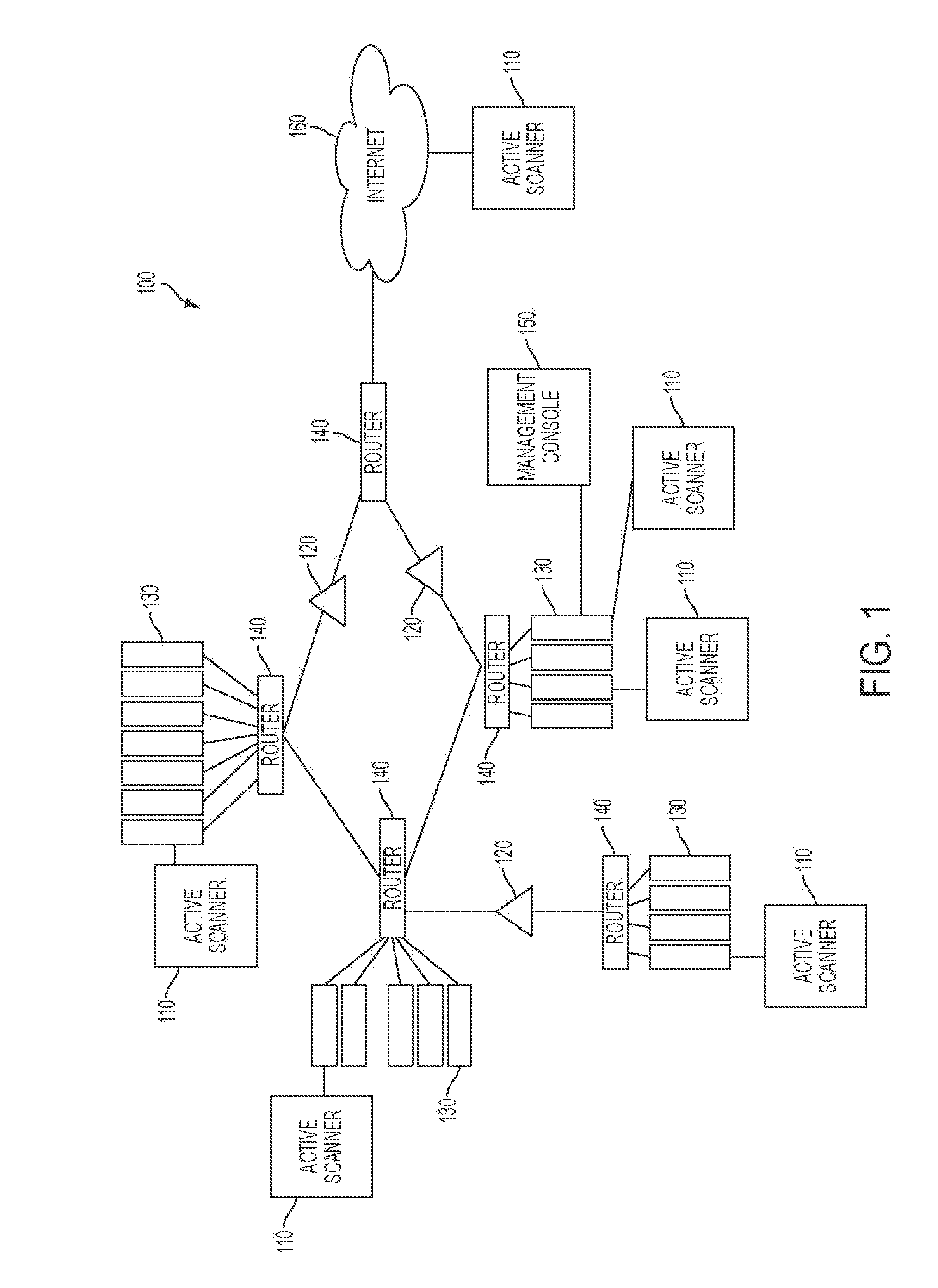
[0029]According to one aspect of the invention, FIG. 1 illustrates an exemplary system 100 to identify exploitable weak points in a network and simulate attacks paths that may potentially exploit the identified weak points in the network. In particular, the system 100 shown in FIG. 1 may generally include one or more active scanners 110 that can communicate packets or other messages within the network to detect new or changed information describing various routers 140, hosts 130, servers 130, or other devices 130 in the network. For example, in one implementation, the active scanners 110 may perform credentialed audits or uncredentialed scans to scan certain hosts 130, servers 130, or other devices 130 in the network and obtain information that may then be analyzed to identify potential vulnerabilities in the network. More particularly, in one implementation, the credentialed audits may include the active scanners 110 using suitable authentication technologies to log into and obtain...


PUM


Abstract

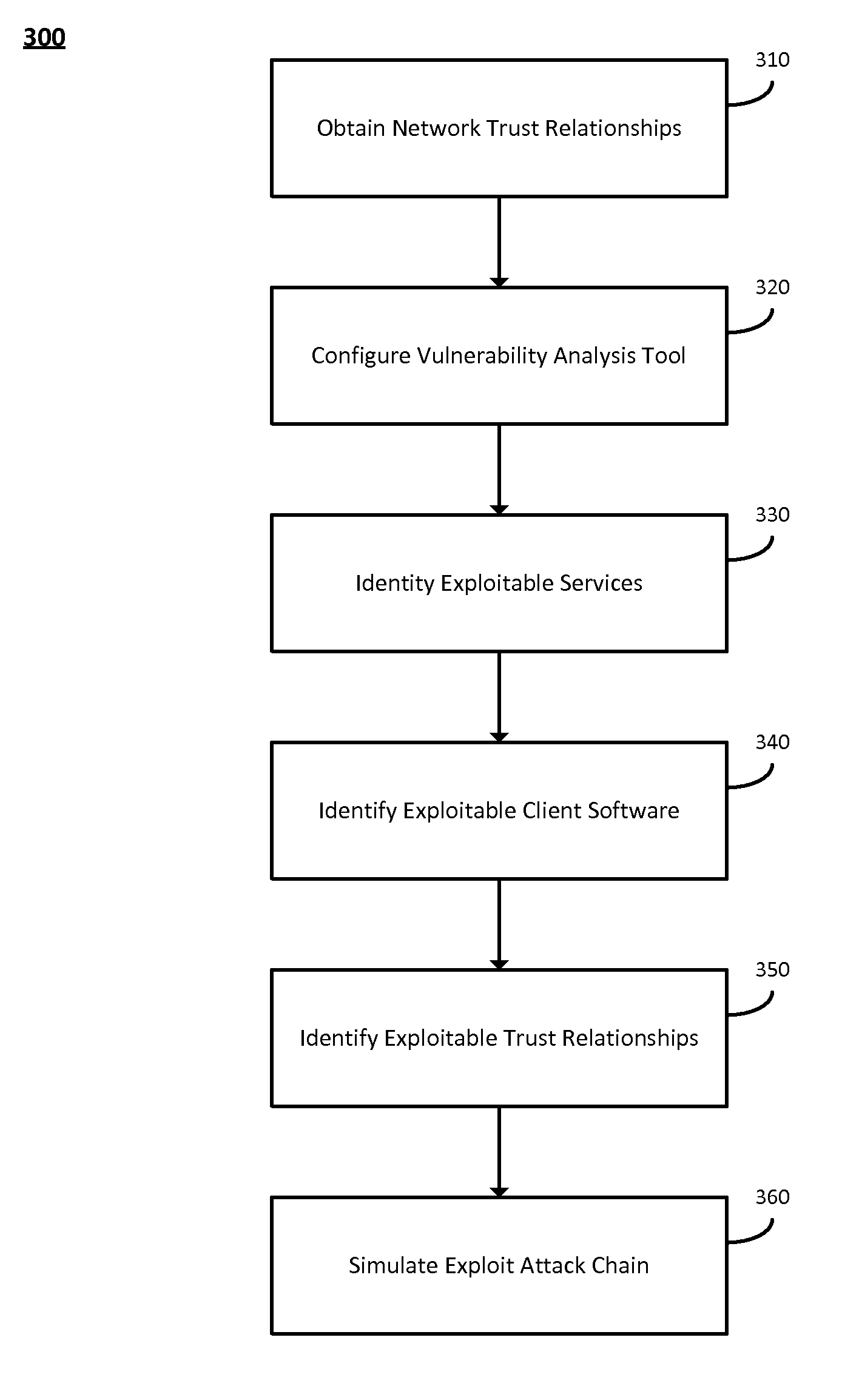
The system and method described herein may leverage passive and active vulnerability discovery to identify network addresses and open ports associated with connections that one or more passive scanners observed in a network and current connections that one or more active scanners enumerated in the network. The observed and enumerated current connections may be used to model trust relationships and identify exploitable weak points in the network, wherein the exploitable weak points may include hosts that have exploitable services, exploitable client software, and / or exploitable trust relationships. Furthermore, an attack that uses the modeled trust relationships to target the exploitable weak points on a selected host in the network may be simulated to enumerate remote network addresses that could compromise the network and determine an exploitation path that the enumerated remote network addresses could use to compromise the network.

Description

CROSS-REFERENCE TO RELATED APPLICATIONS[0001]The present application claims priority under 35 U.S.C. §119(e) to U.S. Provisional Patent Application Ser. No. 61 / 665,107, entitled “System and Method for Identifying Exploitable Weak Points in a Network,” filed Jun. 27, 2012, the contents of which are hereby incorporated by reference in their entirety.FIELD OF THE INVENTION[0002]The invention generally relates to a system and method for identifying exploitable weak points in a network, and in particular, to leveraging active and passive vulnerability discovery to identify remotely visible and exploitable services, client software, and trust relationships and simulate hacking via server-side exploits to enumerate remote network addresses that could potentially exploit the identified weak points in the network.BACKGROUND OF THE INVENTION[0003]In many network environments, illegal or unauthorized users may exploit vulnerabilities in the network to gain access, deny access, or otherwise att...

Claims


Application Information

Patent Timeline
Patent Type & Authority Patents(United States)
IPC IPC(8): G06F21/00H04L29/06
CPCH04L63/1433H04L41/12H04L67/10
Inventor GULA, RONDERAISON, RENAUD
Owner TENABLE INC
Learn More