Hydraulic working machine
a working machine and hydraulic technology, applied in the direction of fluid couplings, hybrid vehicles, electric control of exhaust treatment, etc., can solve the problems of increasing the load on the engine more than necessary, increasing the temperature of exhaust gas, and conventional technology tending to produce energy loss, etc., to achieve high accuracy
- Summary
- Abstract
- Description
- Claims
- Application Information
AI Technical Summary
Benefits of technology
Problems solved by technology
Method used
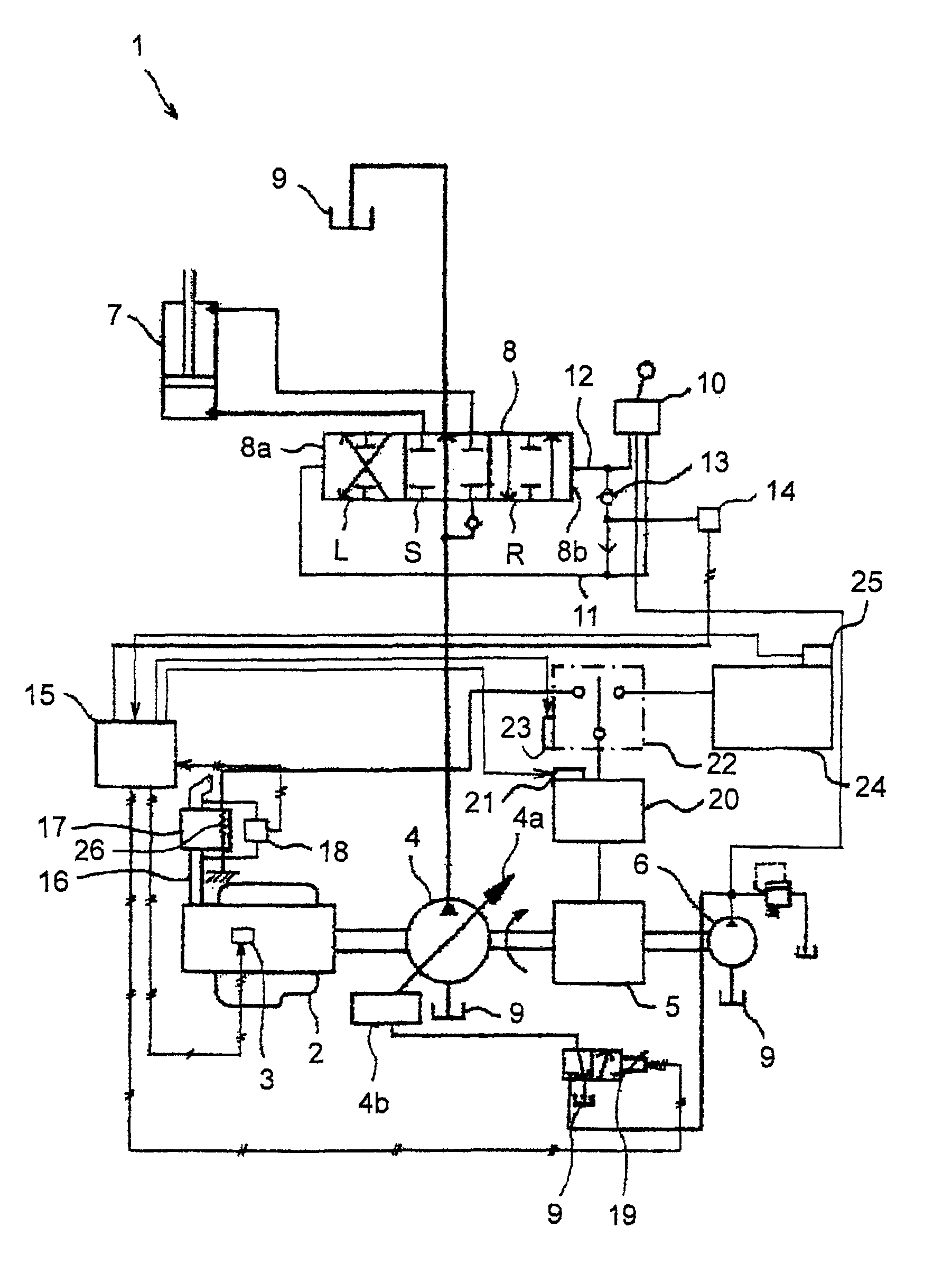
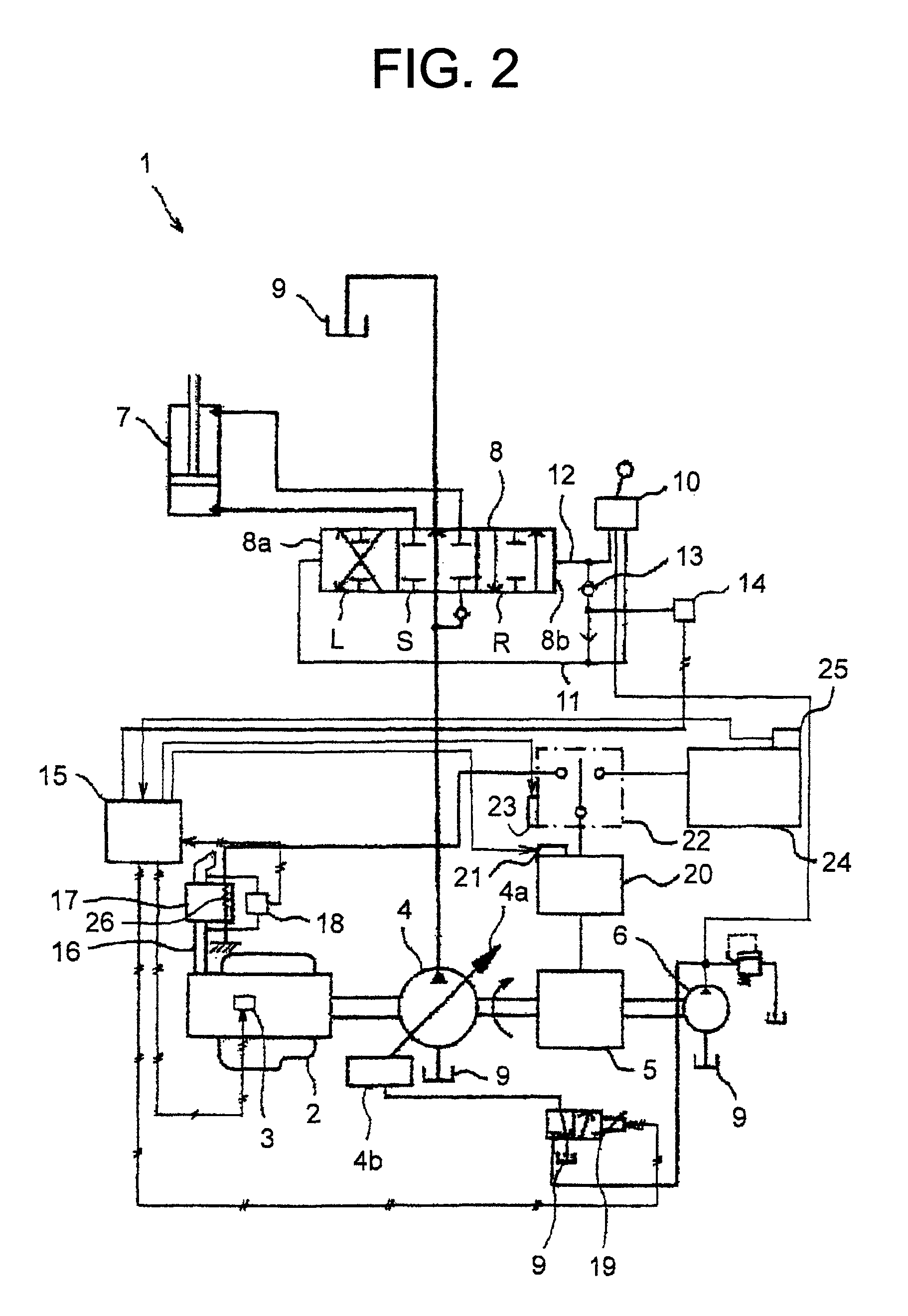
Image

Examples
Embodiment Construction
[0018]One embodiment of the hydraulic working machine according to the present invention will hereinafter be described with reference to the drawings.
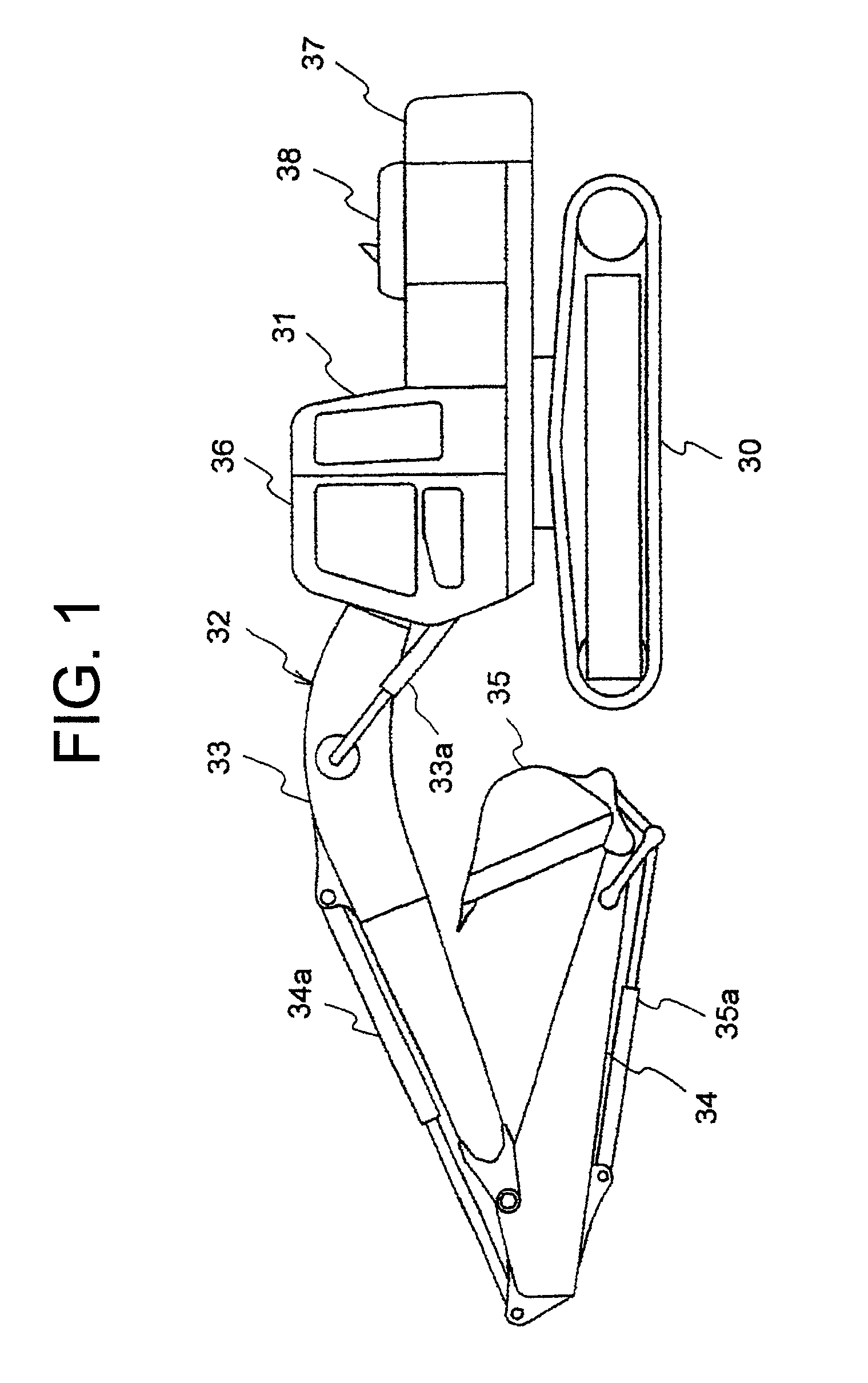
[0019]FIG. 1 is a side view showing a hydraulic excavator as one embodiment of the hydraulic working machine. As shown in FIG. 1, the hydraulic excavator according to this embodiment is provided with a travel base 30, an upperstructure 31 arranged on the travel base 30, and working equipment 32 attached tiltably in an up-and-down direction to the upperstructure 31. The working equipment 32 includes a boom 33 attached tiltably in the up-and-down direction to the upperstructure 31, an arm 34 attached tiltably in the up-and-down direction to a free end of the boom 33, and a bucket 35 attached tiltably in the up-and-down direction to a free end of the arm 34. In addition, the working equipment 32 also includes hydraulic cylinders, specifically hydraulic actuators such as a boom cylinder 33a for actuating the boom 33, an arm cylinder 34a fo...
PUM
 Abstract
Description
Claims
Application Information
 - R&D
- Intellectual Property
- Life Sciences
- Materials
- Tech Scout
- Unparalleled Data Quality
- Higher Quality Content
- 60% Fewer Hallucinations
Browse by: Latest US Patents, China's latest patents, Technical Efficacy Thesaurus, Application Domain, Technology Topic, Popular Technical Reports.
© 2025 PatSnap. All rights reserved.Legal|Privacy policy|Modern Slavery Act Transparency Statement|Sitemap|About US| Contact US: help@patsnap.com