
Wafer processing apparatus with heated, rotating substrate support

a technology of rotating substrates and processing apparatuses, which is applied in the direction of muffle furnaces, charge manipulation, furnaces, etc., can solve the problems of easy affecting the within-wafer temperature uniformity of the lower wafers, difficult control of the lower substrates in the wafer boat, etc., and achieve uniform heating of one or more substrates.

Active Publication Date: 2015-04-28
ASM IP HLDG BV
View PDF11 Cites 341 Cited by
  • Summary
  • Abstract
  • Description
  • Claims
  • Application Information

AI Technical Summary

Benefits of technology

This configuration enhances within-substrate temperature uniformity by rotating the substrate support relative to the heater, reducing the impact of heater non-uniformities and extending the apparatus' lifespan by avoiding high-temperature exposure for critical components.

Problems solved by technology

The simultaneous processing of a plurality of semiconductor wafers in a vertical batch furnace presents the problem of how to subject all wafers that are stacked into a wafer boat to substantially the same process conditions across their respective surface areas.
However, in a vertical batch furnace the temperature of the lower substrates in the wafer boat proves difficult to control.
Although such heating means may increase the wafer-to-wafer temperature uniformity across the wafers of the batch, any non-uniformities in the heating means and / or the heat profile they produce may easily affect the within-wafer temperature uniformity of the lower wafers.

Method used


Image

  • Wafer processing apparatus with heated, rotating substrate support
  • Wafer processing apparatus with heated, rotating substrate support
  • Wafer processing apparatus with heated, rotating substrate support

Examples


second embodiment

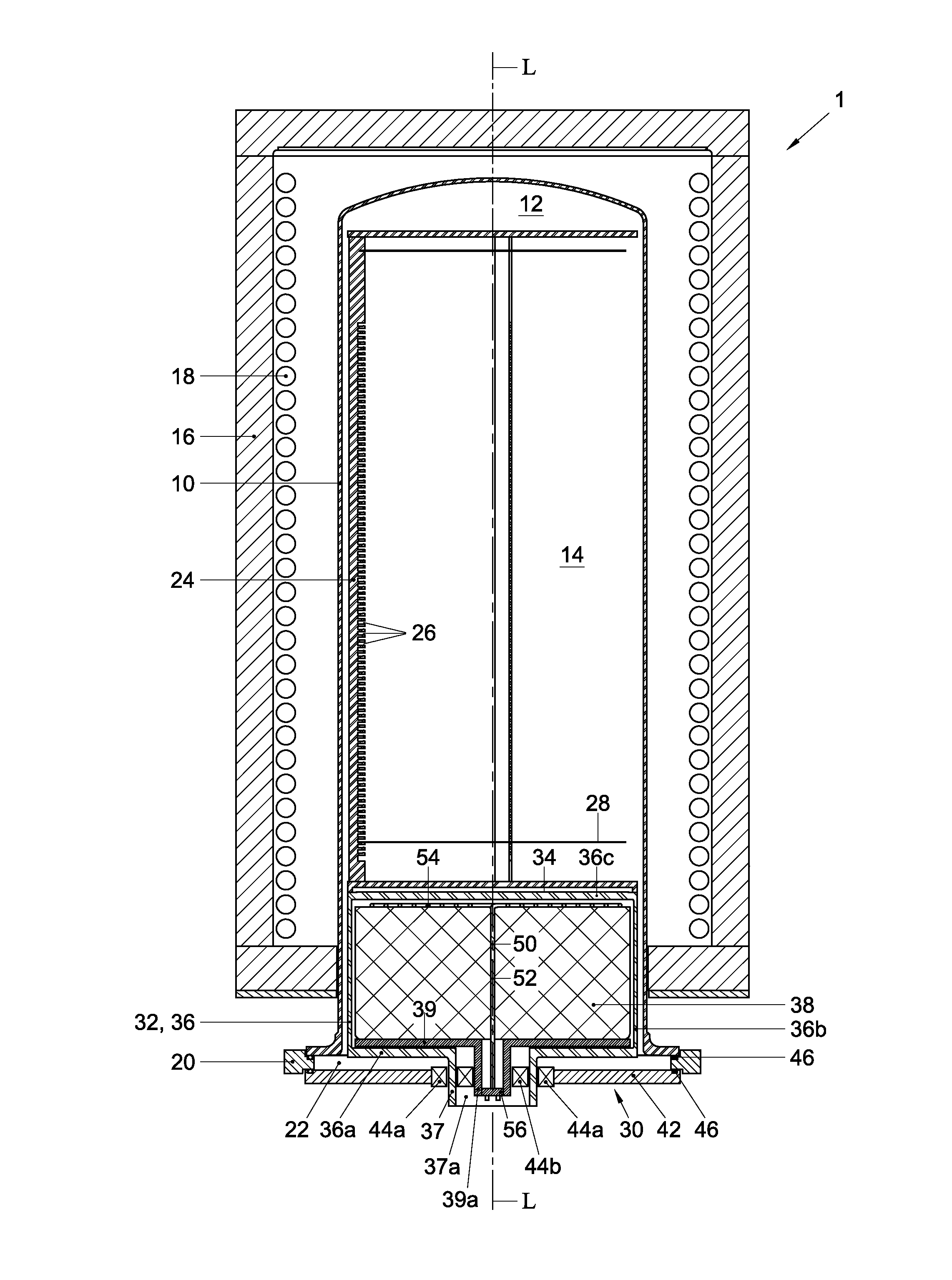
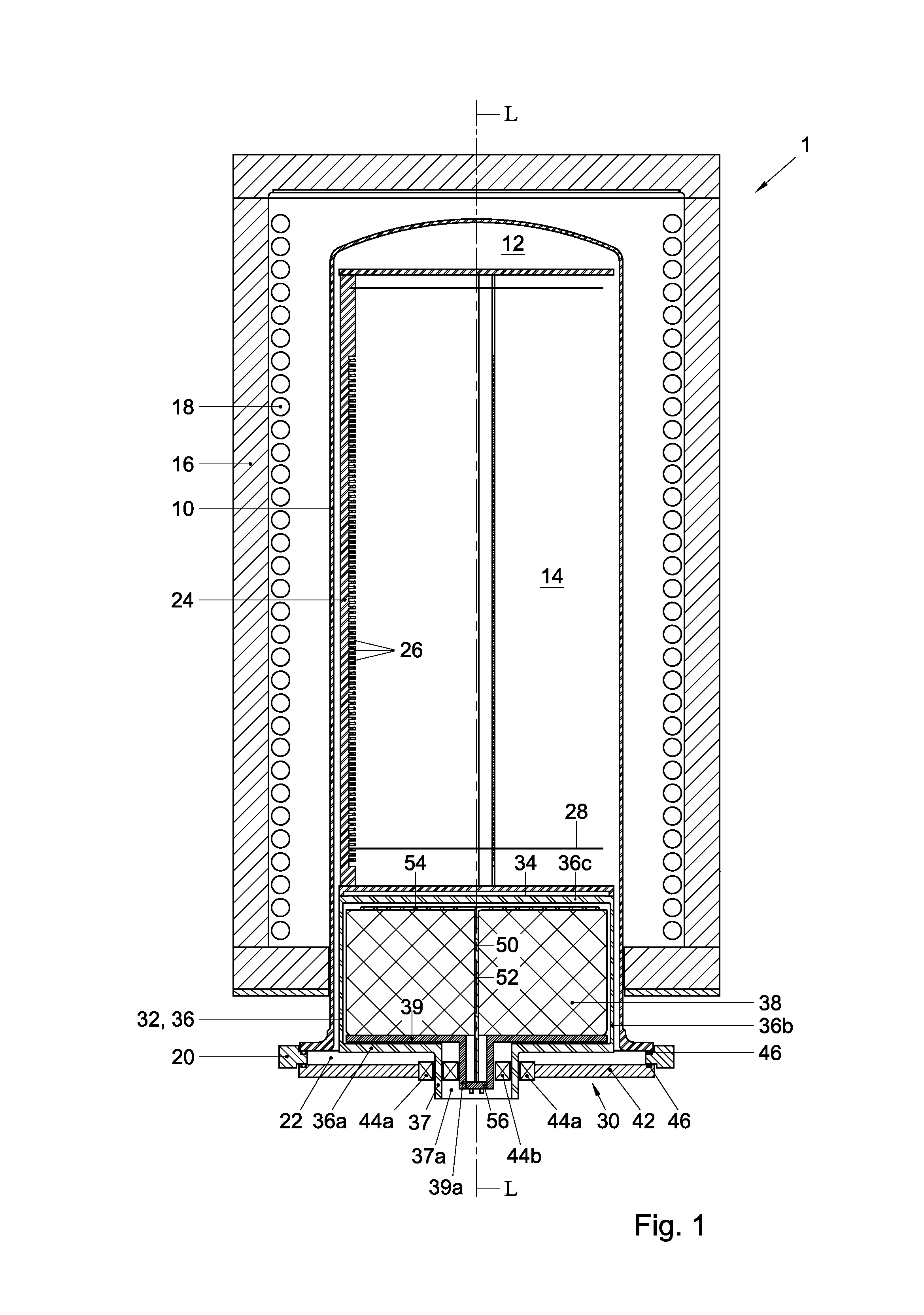
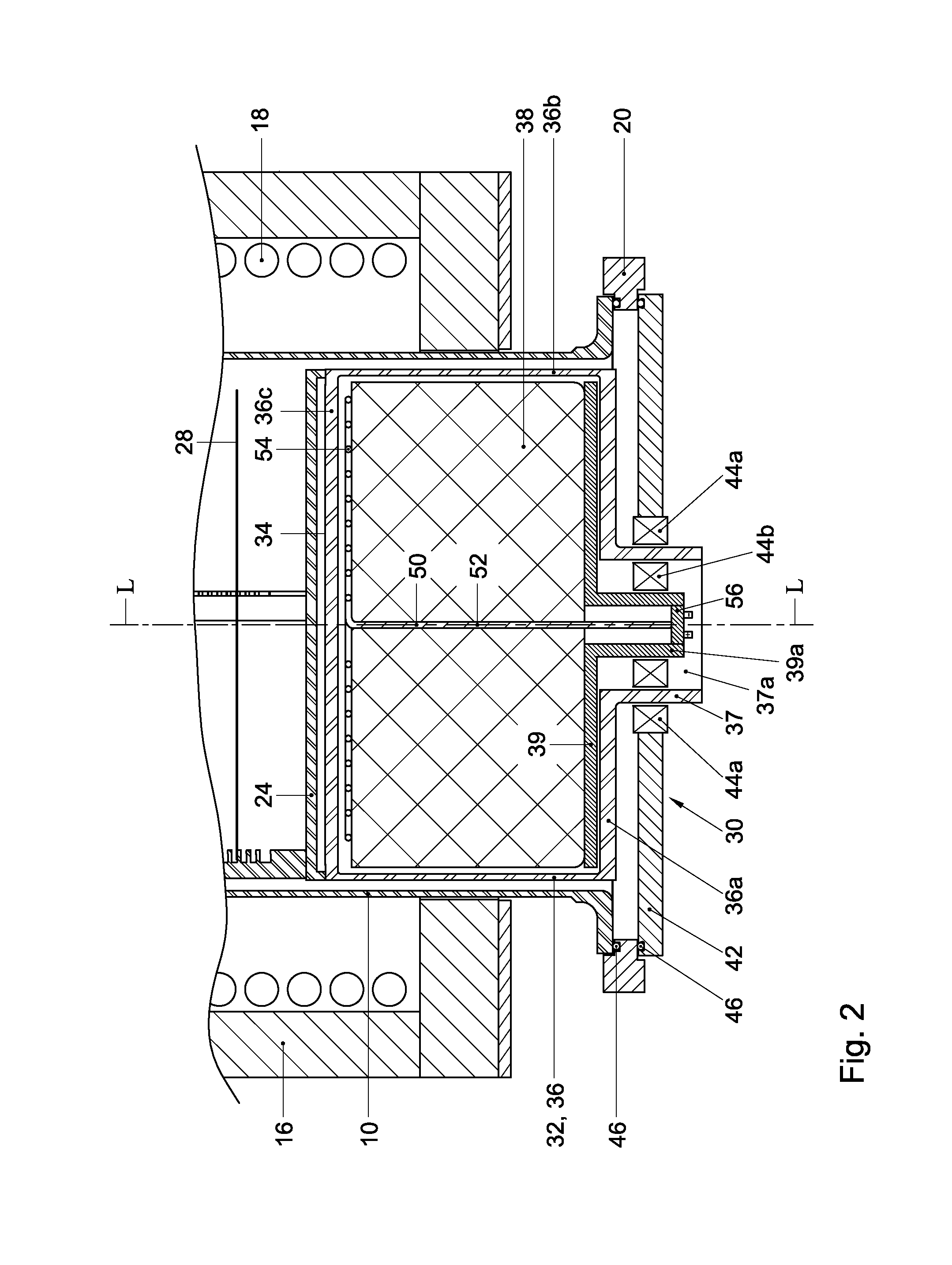
[0031]In the embodiment of FIGS. 3-5 the body of the container 36, extending between the bottom wall 36a and the top wall 36c, may define two body parts. A first body part, adjacent the top wall 36c, may define an interior space for receiving a heat dissipating portion 54 of the heater 50. A second body part, adjacent the bottom wall, may define an interior annular space around the rotation axis L that may be at least partly filled with thermally insulating material 38. It will be clear from FIGS. 3-5 that the furnace 1 does not include a support plate 39 to support the thermally insulating material 38. Instead, the thermally insulating material 38 rests directly on the bottom wall 36c of the container 36, such that it is in a fixed, stationary relationship therewith. That is, the insulating material 38 will move in unison with the container 36 when the latter is rotated.

[0032]To allow the container 36 to be rotated relative to heater 50, the container 36 may define a hollow shaft 4...

first embodiment

[0034]As in FIGS. 1-2, the doorplate 42 may be supported on a loader arm (not shown), which may comprise a socket configured to arrestingly receive the plug 56. When the loader arm is in place, its motor may engage the drive shaft 37 of the substrate support 32, for example through a drive ridge recess 37b provided therein, and drive it to rotate the substrate support 32 and the wafers 28 supported thereon relative to both the heating means 18 and the heat dissipating portion 54 of the heater 50, thereby averaging out the effects that non-uniformities in the heating profile of the heating means 18 and heat dissipating portion 54 of the heater 50 may have on the wafers.

[0035]Although illustrative embodiments of the present invention have been described above, in part with reference to the accompanying drawings, it is to be understood that the invention is not limited to these embodiments. Variations to the disclosed embodiments can be understood and effected by those skilled in the a...


PUM


Abstract

A semiconductor substrate processing apparatus (1), comprising a substrate support assembly (30), including a substrate support (32) defining an outer support surface (34) for supporting a substrate or substrate carrier (24) thereon, and a heater (50) comprising a heat dissipating portion (54) that is disposed within the substrate support (32) and that extends underneath and substantially parallel to the support surface (34), said substrate support (32) being rotatably mounted around a rotation axis (L) that extends through said support surface (34), such that the support surface (34) is rotatable relative to the heat dissipating portion (54) of the heater (50).

Description

FIELD OF THE INVENTION[0001]The present invention relates to the field of semiconductor processing, and more in particular to a semiconductor processing apparatus including a heated, rotating substrate support.BACKGROUND[0002]The simultaneous processing of a plurality of semiconductor wafers in a vertical batch furnace presents the problem of how to subject all wafers that are stacked into a wafer boat to substantially the same process conditions across their respective surface areas. One such process condition is the exposure to process gases. To promote the uniformity of this exposure, a vertical furnace is commonly equipped with a boat rotation mechanism that rotates the wafer boat during processing so as to average out non-uniformities in process gas flows that contact the wafers. Another process condition is the temperature of the wafers. To obtain uniform processing results across the substrates of a batch, each of the wafers thereof may preferably be heated substantially unif...

Claims


Application Information

Patent Timeline
Patent Type & Authority Patents(United States)
IPC IPC(8): F27D5/00F27B17/00H01L21/67
CPCH01L21/67109F27B17/0025H01L21/68714
Inventor DE RIDDER, CHRIS G. M.BOONSTRA, KLAAS P.OOSTERLAKEN, THEODORUS G. M.RAVENHORST, BAREND J. T.
Owner ASM IP HLDG BV
Learn More