
Metering pump with special-shaped cavity

a metering pump and cavity technology, which is applied in the direction of rotary/oscillating piston pump components, machines/engines, liquid fuel engines, etc., can solve the problems that the existing metering pump which mainly rely on the plunger piston type and the diaphragm type cannot meet the development demands, and achieves high pumping efficiency, high metering accuracy, and great fluid pressure increment

Inactive Publication Date: 2015-03-10
ZHEJIANG UNIV
View PDF4 Cites 0 Cited by
  • Summary
  • Abstract
  • Description
  • Claims
  • Application Information

AI Technical Summary

Benefits of technology

The invention is a rotor type metering pump with a special-shaped cavity that has the following technical effects: 1. The structure is simple and reliable, with a high pumping efficiency and a wide range of flow rates, pressures, and viscosities. 2. The special-shaped cavity and rotor design enable a dynamic sealing mechanism, resulting in high metering precision and self-sucking capability. 3. The elastic elements enable automatic compensation for abrasion and anti-sticking, improving the pump's stability and safety. 4. The rotor is incapable of performing reversion, making it ideal for applications where the pressure at the outlet is higher than the pressure at the inlet. 5. The pump can be controlled through both magnetic pulses and mechanically outputted rotation cycles, allowing for flexible regulation and digitized and networked applications. 6. The structure is simple and easy to maintain, with a lower production cost.

Problems solved by technology

Along with the development of the modern industrial technology, the requirements on metering accuracy, working reliability, working life, range of flow rate, adjustability of the flow rate, range of pressure, adaptability of media, corrosion resistance, high-temperature resistance, structural form, driving way, monitoring of working conditions and other aspects of the metering pumps are higher and higher, and the existing metering pumps which mainly rely on the plunger piston type and the diaphragm type cannot meet the development demands.

Method used


Image

  • Metering pump with special-shaped cavity
  • Metering pump with special-shaped cavity
  • Metering pump with special-shaped cavity

Examples


Embodiment Construction

[0040]In combination of the embodiments and the figures, the invention is further described as follows.

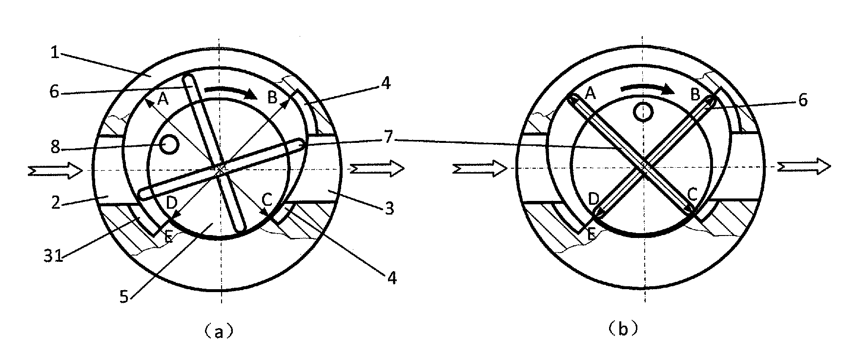
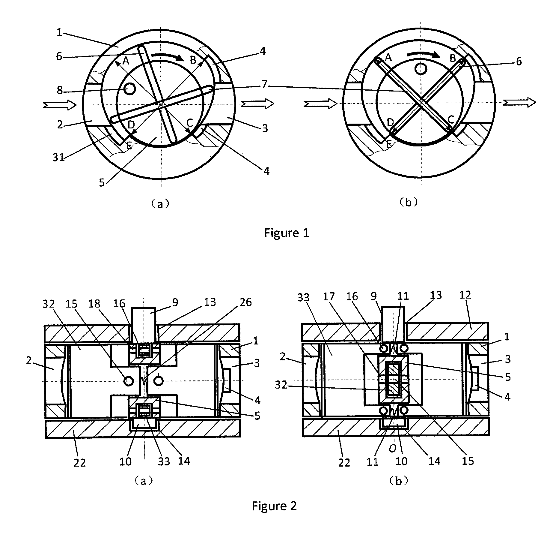
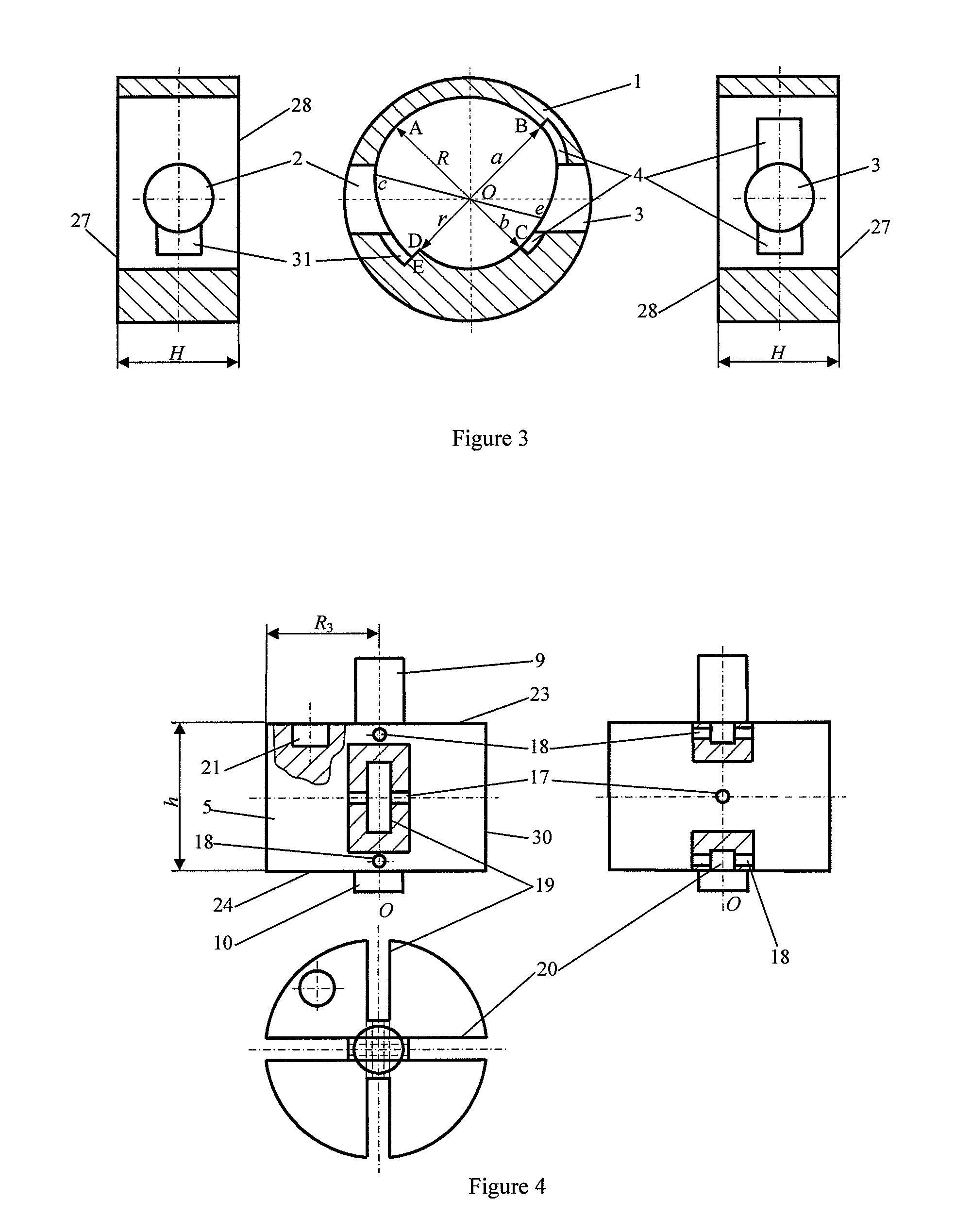
[0041]Embodiment 1: a metering pump with a special-shaped cavity, referring to FIG. 1 to FIG. 8. As for the device, a housing 1 with a special-shaped surface inner cavity, an inlet 2, an outlet 3, a diversion groove 4 and a pressure balancing groove (31), an upper cover plate 12 and a lower cover plate 22 constitute a sealed cavity, wherein the upper cover plate 12 and the lower cover plate 22 are mounted on the two end surfaces of the housing 1, and a rotor is mounted in the sealed cavity.

[0042]The special-shaped surface inner cavity of the housing 1 is formed by sequentially linking a one-quarter circular arc surface AB, a one-quarter oval arc surface BC, a one-quarter circular arc surface CD, a turning transition surface DE and a position-limiting curved surface EA, wherein the one-quarter circular arc surface AB, the one-quarter oval arc surface BC and the one-quarter circular ...


PUM


Abstract

A metering pump with a special-shaped cavity comprising a housing, a rotor and two cover plates. The housing is a cylinder with a special-shaped surface inner cavity formed by combining two circular arc surfaces with two non-circular arc surfaces and a planar surface, an inlet and an outlet. The rotor comprises a rotor body and two pairs of combined sliding plates. The housing is matched with the cover plates for constituting a sealed cavity. When the rotor rotates, the non-circular arc surface of the special-shaped surface inner cavity can enable the two pairs of the combined sliding plates to slide in a cross manner so as to suck in fluid from the inlet and press out the fluid from the outlet. When the rotor rotates one cycle, four standard volumes are formed in a cavity body and the equal quantity of the fluid flows by the cavity body.

Description

TECHNICAL FIELD[0001]The invention relates to a metering pump with a special-shaped cavity, which belongs to the field of metering technologies and fluid machinery technologies.BACKGROUND OF THE INVENTION[0002]Metering pumps are widely applied in chemical industry, energy, machinery, paper-making, spinning, pharmacy, water treatment and other fields, and the main types of the metering pumps comprise plunger piston metering pumps and diaphragm metering pumps.[0003]Along with the development of the modern industrial technology, the requirements on metering accuracy, working reliability, working life, range of flow rate, adjustability of the flow rate, range of pressure, adaptability of media, corrosion resistance, high-temperature resistance, structural form, driving way, monitoring of working conditions and other aspects of the metering pumps are higher and higher, and the existing metering pumps which mainly rely on the plunger piston type and the diaphragm type cannot meet the deve...

Claims


Application Information

Patent Timeline
Patent Type & Authority Patents(United States)
IPC IPC(8): F01C1/00F03C2/00F04C2/00F03C4/00F01C21/08F01C21/10F04C2/344F04C15/00
CPCF04C2/3441F01C21/0845F01C21/106F04C15/0049F04C2220/24F04C2250/301
Inventor LU, YANGLEI, HUA
Owner ZHEJIANG UNIV
Learn More