
Actinic ray-sensitive or radiation-sensitive resin composition and method of forming pattern with the composition

a technology of radiation-sensitive resin and resin composition, which is applied in the direction of photosensitive materials, instruments, photomechanical equipment, etc., can solve the problems of unsatisfactory above-mentioned chemical amplification system, unsatisfactory acid generator in many respects, and dirty exposure apparatus

Active Publication Date: 2014-12-02
FUJIFILM CORP
View PDF26 Cites 24 Cited by
  • Summary
  • Abstract
  • Description
  • Claims
  • Application Information

AI Technical Summary

Benefits of technology

The present invention provides an actinic ray-sensitive or radiation-sensitive resin composition that has improved sensitivity, resolution, roughness characteristic, pattern profile, and outgas characteristic. This is achieved by using a novel compound obtained by introducing a specified substituent in a sulfonate anion, which inhibits the diffusion of any generated acid and enhances the resolution and roughness characteristic of the photosensitive composition. The resin composition can also contain a dissolution inhibiting compound of 3000 or less molecular weight to improve its solubility in an alkali developer. Additionally, the resin composition can further contain a basic compound and / or a fluorinated and / or siliconized surfactant to further improve its performance.

Problems solved by technology

On the other hand, in using a light source of a further shorter wavelength, for example, an ArF excimer laser (193 nm) as an exposure light source, as the compounds having aromatic groups inherently exhibit a sharp absorption in the region of 193 nm, the above-mentioned chemical amplification system has not been satisfactory.
However, this acid generator is unsatisfactory in many respects.
This would cause any low-boiling-point compounds, such as solvents, and resist materials decomposed by high energy to evaporate to thereby dirty the exposure apparatus.
This outgas problem is attracting greater attention.

Method used


Image

  • Actinic ray-sensitive or radiation-sensitive resin composition and method of forming pattern with the composition
  • Actinic ray-sensitive or radiation-sensitive resin composition and method of forming pattern with the composition
  • Actinic ray-sensitive or radiation-sensitive resin composition and method of forming pattern with the composition

Examples


example

[0620]The present invention will be described in greater detail below with reference to its examples. However, the subject matter of the present invention is in no way limited to these examples.

[0621]

[0622](1) Synthesis of compound A1-1

[0623]

[0624]Aluminum chloride amounting to 6.83 g was added to 20.0 g of benzene and agitated while cooling at 3° C. Then, 40.4 g of cyclohexyl chloride was slowly dropped thereinto. After the completion of the dropping, the mixture was agitated at room temperature for 5 hours and poured into ice water. An organic layer was extracted by use of ethyl acetate, and the obtained organic layer was distilled at 40° C. under reduced pressure and further at 170° C. under reduced pressure. The resultant matter was cooled to room temperature, and 50 ml of acetone was poured thereinto to thereby carry out recrystallization. The crystal obtained by the recrystallization was collected by filtration. Thus, 14 g of tricyclohexylbenzene was obtained.

[0625]

[0626]Tricy...

example b

[0718]A resist solution was prepared according to exactly the same procedure as in Example A except that 0.06 g of the polymer shown below was added to the photosensitive composition of the Example 1A. The resist solution was applied in the same manner, thereby obtaining a resist film. The obtained resist film was patternwise exposed through a liquid for liquid immersion (pure water) by use of an ArF excimer laser liquid immersion scanner (manufactured by ASML, XT1250i, NA0.85), thereby attaining the same pattern formation as in Example A. It was ascertained that in all of the sensitivity, resolving power (y), line edge roughness and pattern profile, the same evaluation results were obtained on the obtained patterns.

[0719]

example c

Examples 1C to 16C and Comparative Examples 1C and 2C

[0720]

[0721]Referring to Table 2 below, with respect to each of the resists, the individual components were dissolved in the solvent and passed through a polytetrafluoroethylene filter of 0.1 μm pore size, thereby obtaining a positive resist solution of 14 mass % solid content.

[0722]

[0723]Each of the obtained positive resist solutions was uniformly applied onto a silicon substrate having undergone a hexamethyldisilazane treatment by use of a spin coater, and heated and dried on a hot plate at 120° C. for 90 seconds, thereby obtaining a 0.4 μm resist film.

[0724]The obtained resist film was patternwise exposed through a line-and-space mask by use of a KrF excimer laser stepper (NA=0.63). Immediately after the exposure, the resist film was heated on a hot plate at 110° C. for 90 seconds. Thereafter, the resist film was developed with a 2.38 mass % aqueous tetramethylammonium hydroxide solution at 23° C. for 60 seconds, rinsed with pu...


PUM

PropertyMeasurementUnit
wavelengthaaaaaaaaaa
roughnessaaaaaaaaaa
mol %aaaaaaaaaa

Abstract

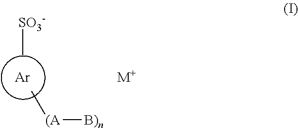
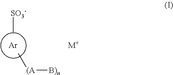
An actinic ray-sensitive or radiation-sensitive resin composition includes any of the compounds of general formula (I) below;wherein:Ar represents an aromatic ring that may have a substituent other than the -(A-B) groups;n is an integer of 1 or greater;A represents any one, or a combination of two or more members selected from a single bond, an alkylene group, —O—, —S—, —C(═O)—, —S(═O)—, —S(═O)2— and —OS(═O)2—, provided that —C(═O)O— is excluded;B represents a group containing a hydrocarbon group having 4 or more carbon atoms wherein either a tertiary or a quaternary carbon atom is contained,when n is 2 or greater, the two or more -(A-B) groups may be identical to or different from each other; andM+ represents an organic onium ion.

Description

CROSS-REFERENCE TO RELATED APPLICATIONS[0001]This is a Continuation Application of PCT Application No. PCT / JP2009 / 067292, filed Sep. 28, 2009, which was published under PCT Article 21(2) in English.[0002]This application is based upon and claims the benefit of priority from prior Japanese Patent Applications No. 2008-249192, filed Sep. 26, 2008; and No. 2009-039905, filed Feb. 23, 2009, the entire contents of both of which are incorporated herein by reference.BACKGROUND OF THE INVENTION[0003]1. Field of the Invention[0004]The present invention relates to an actinic ray-sensitive or radiation-sensitive resin composition that when exposed to actinic rays or radiation (electron beams, X-rays, EUV, UV, etc.), makes a reaction to thereby have its properties changed and also relates to a method of forming a pattern by use of the composition. More particularly, the present invention relates to an actinic ray-sensitive or radiation-sensitive resin composition employed in a semiconductor pro...

Claims


Application Information

Patent Timeline
Patent Type & Authority Patents(United States)
IPC IPC(8): G03F7/028G03F7/038C07C309/35G03F7/004C07C309/59C07C309/39C07D339/08C07C309/44C07C309/38C07C381/12C07C309/25C07D209/82G03F7/039C07C309/29G03F7/04C07C309/42G03F7/28C07C323/66C07C309/28
CPCC07C2101/18G03F7/0397C07C2102/28C07D339/08G03F7/0392C07C381/12C07C2103/74G03F7/0045C07C309/44C07C309/29C07C2103/28C07C309/38C07C2101/14C07C2102/44C07C309/42C07C2102/42C07C2103/24C07C2101/04C07C309/35C07C309/59C07C2101/08C07C323/66G03F7/0382C07C2101/02C07C309/25C07D209/82Y10S430/122C07C309/39C07C2601/02C07C2601/04C07C2601/08C07C2601/14C07C2601/18C07C2602/28C07C2602/42C07C2602/44C07C2603/24C07C2603/28C07C2603/74C07C309/28G03F7/0047
Inventor TSUCHIMURA, TOMOTAKASHIRAKAWA, KOJITSUCHIHASHI, TORUTSUBAKI, HIDEAKI
Owner FUJIFILM CORP
Learn More