
Real time eye tracking for human computer interaction

a technology of computer interaction and eye tracking, applied in the field of real-time eye tracking for human computer interaction, can solve the problems of reducing the reflectivity of the retina of contact lenses, affecting the user's experience, and affecting the user's perception, so as to achieve more intelligent behavior, increase flexibility, and facilitate interaction

Active Publication Date: 2014-11-11
THE RES FOUND OF STATE UNIV OF NEW YORK
View PDF259 Cites 264 Cited by
  • Summary
  • Abstract
  • Description
  • Claims
  • Application Information

AI Technical Summary

Benefits of technology

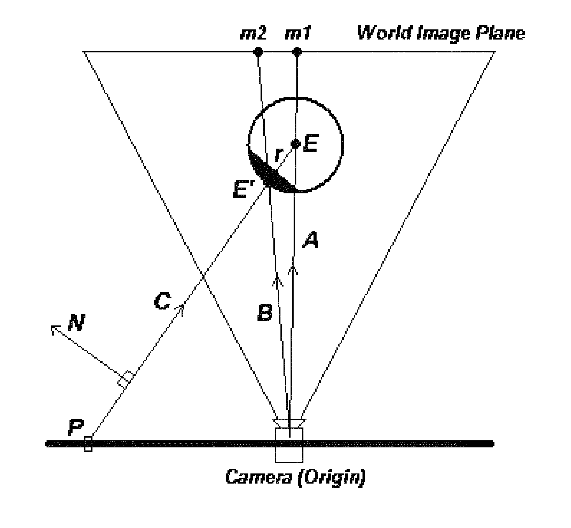
The patent describes a system and method for capturing the direction of a person's eyes using a wide-angle camera and an eye detector. This allows for intuitive user interactions and more intelligent behavior. The system can detect the eye region and estimate its position in 3D using a calibration approach. This information is then used to guide a pan-tilt-zoom camera to focus on the eye area. The system is calibrated to account for head pose adjustments and allows for unrestricted user movement relative to the camera. This allows for natural and non-intrusive eye tracking without the need for infrared light or special hardware setups. The system uses a color video image and is capable of mapping the position of a screen relative to the camera. The visual axis direction is estimated based on the optical axis of the eye and the position of the fovea. The use of a two-camera system further enhances the system's ability to detect and track the face and eye.

Problems solved by technology

The resulting situation can be prodigiously inconvenient and uncomfortable for the user.
While robust to visible light conditions, these methods have issues with changes in head pose, reflections off glasses, and even decreased reflectivity of the retina from contact lenses [9].
An alternative approach is to use stereo cameras [2][11]; while robust, these systems generally require substantial calibration time.
Some complex systems (like “smart rooms” [1]) require expensive and / or non-portable setups.
Even existing, non-stereo, two-camera systems [16] often restrict the user to a preset location in the room.
However, different subjects, head pose changes, and lighting conditions could significantly diminish the quality of the segmentation [20].
This results in a screen that can only be read by the current user, and not by any other onlooker.

Method used


Image

  • Real time eye tracking for human computer interaction
  • Real time eye tracking for human computer interaction
  • Real time eye tracking for human computer interaction

Examples


Embodiment Construction

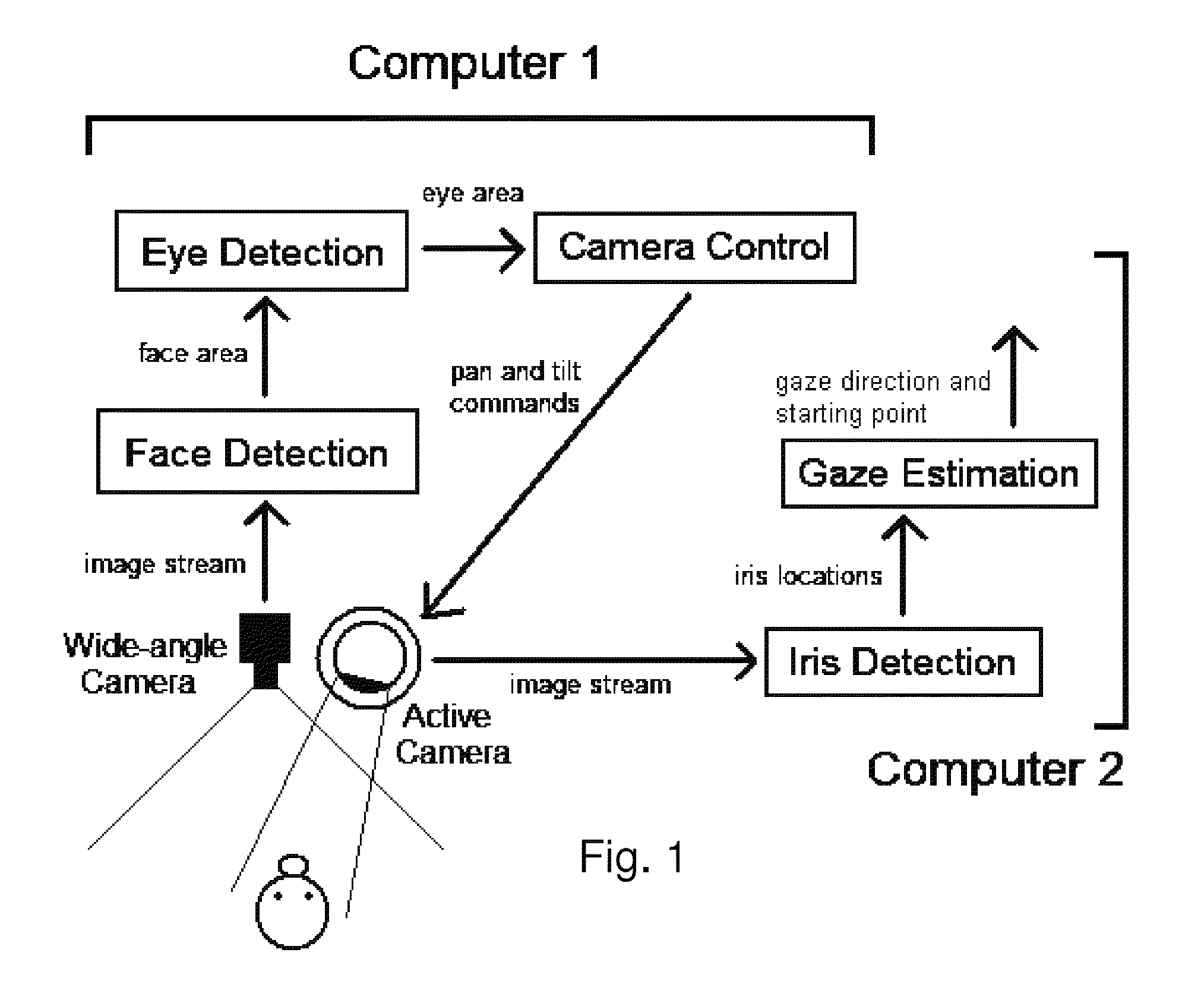
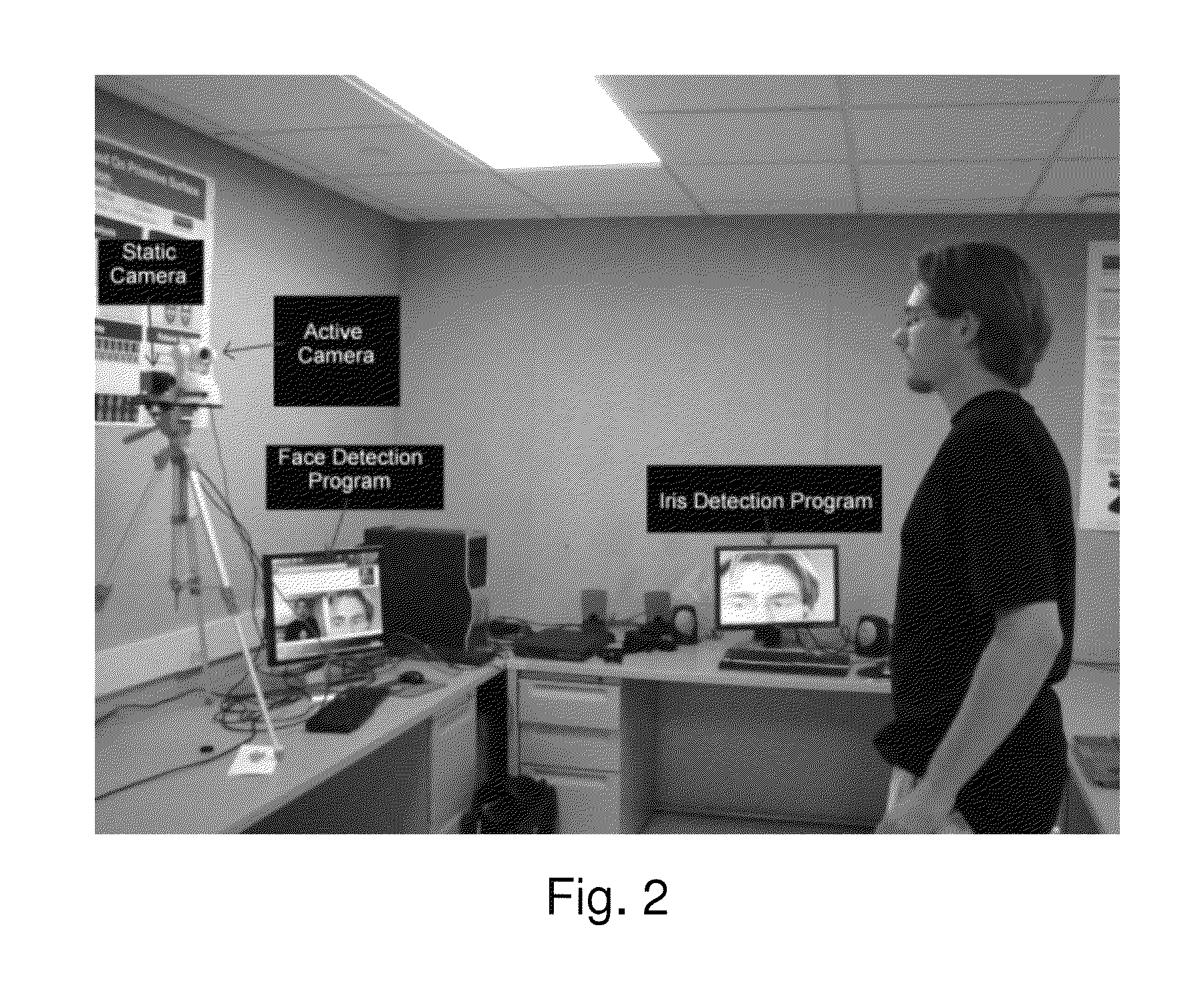
[0062]The complete system consists of five different stages: face detection, eye area detection (wide-angle view), camera control, iris detection (narrow-angle view), and gaze calibration / estimation (narrow-angle view). The first three are part of one program, while the last two are part of another; these two programs run on separate computers. According to one embodiment, an IEEE 1394 camera is used for the wide-angle view; images from this camera are used for face detection. Once a face and eye area center are detected, the detection program controls a SONY SNC-RZ30N camera, which can pan ±170° and tilt from −90° to +25°. It also has a 25× optical zoom. This camera gives us a close-up view of the face (640×480 images at approximately 15 to 30 fps), which can then be used by the eye detection program. FIG. 1 depicts the system composition, while FIG. 2 depicts the system in action. In the integrated system, the gaze estimation uses the active camera view, and the iris centers and c...


PUM


Abstract

A gaze direction determining system and method is provided. A two-camera system may detect the face from a fixed, wide-angle camera, estimates a rough location for the eye region using an eye detector based on topographic features, and directs another active pan-tilt-zoom camera to focus in on this eye region. A eye gaze estimation approach employs point-of-regard (PoG) tracking on a large viewing screen. To allow for greater head pose freedom, a calibration approach is provided to find the 3D eyeball location, eyeball radius, and fovea position. Both the iris center and iris contour points are mapped to the eyeball sphere (creating a 3D iris disk) to get the optical axis; then the fovea rotated accordingly and the final, visual axis gaze direction computed.

Description

CROSS REFERENCE TO RELATED APPLICATIONS[0001]The present application claims benefit of priority from U.S. Provisional Patent Application Ser. No. 61 / 507,780, filed Jul. 14, 2011, the entirety of which is expressly incorporated herein by reference.GOVERNMENT RIGHTS CLAUSE[0002]This invention was made with government support under FA8750-08-0096 awarded by the United States Air Force. The government has certain rights in the invention.BACKGROUND OF THE INVENTION[0003]The ideal human-computer interaction system should function robustly with as few constraints as those found in human-to-human interaction. One of the most effective means of interaction is through the behavior of the eye. Specifically, knowledge of the viewing direction and thus the area of regard offers insight into the user's intention and mental focus, and consequently this information is vital for the next generation of user interfaces [21][22]. Applications in this vein can be found in the fields of HCI, security, ad...

Claims


Application Information

Patent Timeline
IPC IPC(8): G06K9/00
CPCG06K9/00597G06F3/00G06T7/0042G06T2207/30201G06T7/73G06F3/013G06V40/18G06V40/20G06V40/19G06V40/165G06V40/193
Inventor YIN, LIJUNREALE, MICHAEL
Owner THE RES FOUND OF STATE UNIV OF NEW YORK
Learn More